Installation and First Start-Up
- 29 -
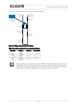
Figure 9: Installation circuit diagram of LIMAX33 CP-00 (minimum configuration)
Weight and
swing protection
Magnetic Tape
AB20-80-10-1-R-D-15BK80
1
2
Upper
fixation
24 V
GND
1
to
presence
detector
from
presence
detector
Presence
detector
LIMAX33CP-00
CAN_H
CAN_L
CAN-GND
CAN-H
System boundary of
LIMAX33CP
Lift Control
Brake
2
OC*)
front doors
OC-I
Recall
DOWN
Recall
UP
Recall
AC supply of
Safety circuit
Main
contactors
Safety circuit
Supply CAN
Safety gear supply
Cut safety circuit
Power
supply
24 VDC GND
rear doors
shield
Inspecti on
DOWN
Inspecti on
UP
Inspecti on
swi tch
OC-O
CAN-L
SHLD
CAN-G
*) Only symbolic; actually
the actuator consists
of 2 relays
Summary of Contents for LIMAX33 CP-00 SERIES
Page 91: ...91 Notes...

