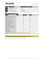
Configured/settable Parameter and Features
- 76 -
14.1.3
Configuration of enabled actuators
General remarks concerning the relationship between “relay-contacts”, “relays” and “actuators”:
An actuator which appears to the outside when the device is regarded as a black box is the either a dry-contact
(concerning OC, SR1 and SR2) or a solid state switch (concerning SGC)
Enabling/disabling of actuators are also configuration features. Additional to the safety functions the needed
actuators must be enabled. An actuators which is physical available on the device but not enabled will always
stay open.
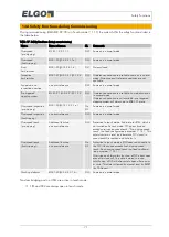
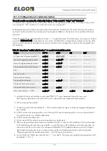
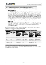
Table 23: dependency “enabled safety functions” => needed actuators. The table shows an overview: if at least
one of the black and bold printed features in a column is fulfilled, the corresponding actuators on the top of the
column must be physically available on the device, enabled in the configuration and correctly integrated in the
lift installation.
Table 23: dependency “enabled safety functions” => needed actuators/relay contacts
Feature
OC **)
eSGC
SR1
SR2
6)
All “inspection” functions disabled” *)
enabled
don’t’ care
1)
don’t care
don’t care
Upper pre-triggered stopping system
enabled
enabled
1)7)
don’t care
don’t care
lower pre-triggered stopping system
enabled
enabled
1)
don’t care
don’t care
Overspeed Inspection (final tripping)
enabled
enabled
don’t care
don’t care
ETSL
enabled
don’t care
don’t care
don’t care
Final Limit switch
enabled
don’t care
don’t care
don’t care
Overspeed (pre tripping)
enabled
don’t care
don’t care
don’t care
Overspeed (final tripping)
enabled
enabled
4)
don’t care
don’t care
Overspeed Teach (pre tripping)
enabled
don’t care
don’t care
don’t care
Overspeed Teach (final tripping)
enabled
enabled
don’t care
don’t care
Doors (door-br UCM)
enabled
2)
enabled
3)
enabled
SR2 optional
5)
*) all safety-functions activated by an activated “EN81-21”-input: overspeed inspection pre- and
final-tripping, upper/lower inspection limit switch, upper/lower pre-triggered stopping system.
**) OC must always be enabled.
1)
“Inspection-safety functions disabled” = NO is a prerequisite for upper or lower pre-triggered stopping sys-
tem enabled
2)
If UCM is solved by opening safety circuit. Solving UCM only by opening safety circuit is only permitted if
the machine brake is a certified safety brake.
3)
If UCM is solved by safety gear.
4)
In this case eSGC must be connected to an electronic safety gear.
5)
SR2 may be optimally enabled and wired additional to SR1 in case of a lift installation with two entry sides.
In lift installations with only one entry side SR1 is used. But also in lift installations with two entry sides, de-
vices with only SR1 may be used. The software of LIMAX33 CP-00 adepts its behavior due to CANopen –
door bridging message by its own in case of only one SR and double-sided entries, refer to Appendix
“Bridging operations for double sided floors” in the CANopen Specification.
6)
In case of feature “Safety gear trip direction” = “only down”, the upper pre-triggered stopping system must
be disabled
Summary of Contents for LIMAX33 CP-00 SERIES
Page 91: ...91 Notes...


