9
Step 7
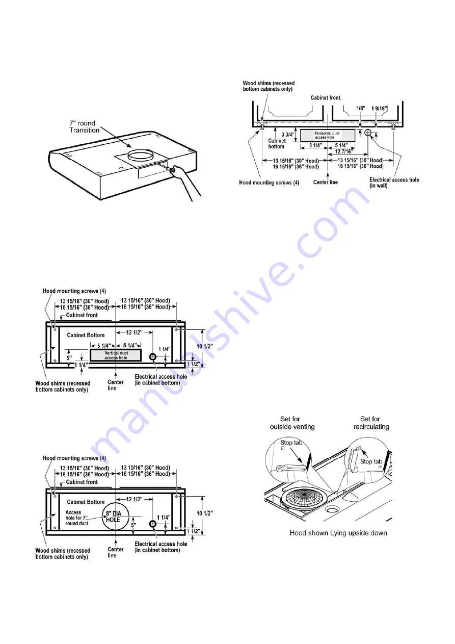
For round ducted discharge installations only
Re-install the round transition with its screws.
NOTE:
The round transition can be installed up to 1
inch on either side of the hood center to
accommodate off-center ductwork. In extreme offcenter
installations, one end of the duct connector
may need to be trimmed to clear the electrical cable
clamp.
Step 8
Mark holes
Select the vent option that your installation will
require and proceed to that section:
Outside top exhaust
(Vertical duct– 3 1/4”x 10” Rectangular)
Use the diagram or the hood as a template and mark
the locations on the cabinet for ductwork, electrical
wiring and keyhole screw slots.
Outside top exhaust
(Vertical duct–7” Round)
Use the diagram or the hood as a template and
mark the locations on the cabinet for ductwork,
electrical wiring and keyhole screw slots.
Outside rear exhaust
(Horizontal duct– 3 1/4”x 10” Rectangular)
• Use the diagram or the hood as a template and mark the
locations on the cabinet for ductwork, electrical wiring and
keyhole screw slots.
Recirculating
Use the hood as a template and mark the locations
on the cabinet for the electrical wiring and keyhole
screw slots.
Since the hood is to be recirculated (not to be vented
outside), do not cut out any vent openings in the wall
or cabinet bottom.
Step 9
Choose Venting Option
The hood can be set to vent outside or to recirculate
air back into the kitchen.
The plastic vent lever is located near the center of the
hood opening.
To vent to the outside, make sure the plastic vent
lever is in the HORIZONTAL position (flat against the
metal top of the hood).
To recirculate air into the kitchen, make sure the
plastic vent lever is in the VERTICAL position (flat
against the plastic blower housing).
NOTE:
In order to change the vent lever position, you
will need to pull the lever out slightly to clear the
plastic tabs.
Summary of Contents for EBL436BL
Page 6: ...6 Dimensions and Clearances ...
Page 21: ...21 Dimensions et Dégagement ...


