8
A
A
A.
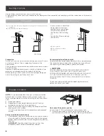
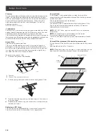
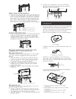
Lateral panels
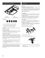
• Install 3
1
⁄
4
x 10” (8.3 x 25.4 cm) vent connector, depending
on the vent system installation.
NOTE:
The 3
1
⁄
4
x 10” (8.3 x 25.4 cm) rectangular vent connector
can be installed up to 1” (2.5 cm) on either side of the hood
center to accommodate off center ductwork.
B
B
C
A
D
A. Vertical connector
B. 6.5 x 9.5 mm screws
C. Vent knockouts
D. Horizontal connector
• For round installation: Install 7” (17.8 cm) round vent
mounting plate and damper (purchase as an accesory).
A
B
C
E
D
A. 7” (17.8 cm) round damper
B. Sheet metal screws
C. 7” (17.8 cm) round vent mounting plate
D. Round vent knockout
E. Rectangular vent knockout
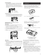
• If a vent damper is installed with a wall cap with damper,
check to make sure they do not interfere with each other.
Remove the vent connector damper flap if they interfere.
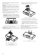
Non-ducted (recirculating) installations - No vent attachments.
It requires the removal of the recirculation cover plate.
Remove the two screws from the recirculation cover plate and
remove.
A
B
A.
Screws (2)
B.
Recirculation cover plate
Electrical Connection
I
WARNING
Electrical Shock Hazard
I
WARNING
Turn off power circuit at the service panel before wiring this
unit. 120 VAC, 15 or 20 Amp circuit required.
ELECTRICAL GROUNDING INSTRUCTIONS
THIS APPLIANCE IS FITTED WITH AN ELECTRICAL JUNCTION
BOX WITH 3 WIRES, ONE OF WHICH (GREEN/YELLOW)
SERVES TO GROUND THE APPLIANCE. TO PROTECT YOU
AGAINST ELECTRIC SHOCK, THE GREEN AND YELLOW WIRE
MUST BE CONNECTED TO THE GROUNDING WIRE IN YOUR
HOME ELECTRICAL SYSTEM, AND IT MUST UNDER NO
CIRCUMSTANCES BE CUT OR REMOVED.
Failure to do so can result in death or electrical shock.
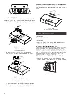
• Remove the knockout and the Junction box cover and
install the conduit connector (cULus listed) in junction box.
A
A.
Terminal box cover


