14
Electrical connection
WARNING
Electrical Shock Hazard
Warning: Turn off power circuit at the service panel
before wiring this unit.
120 VAC, 15 or 20 Amp circuit required.
ELECTRICAL
GROUNDING
INSTRUCTIONS
THIS APPLIANCE IS FITTED WITH AN ELECTRICAL
JUNCTION BOX WITH 3 WIRES, ONE OF WHICH
(GREEN/YELLOW) SERVES TO GROUND THE
APPLIANCE. TO PROTECT YOU AGAINST
ELECTRIC SHOCK, THE GREEN AND YELLOW WIRE
MUST BE CONNECTED TO THE GROUNDING WIRE
IN YOUR HOME ELECTRICAL SYSTEM, AND IT
MUST UNDER NO CIRCUMSTANCES BE CUT OR
REMOVED.
Failure to do so can result in death or electrical
shock.
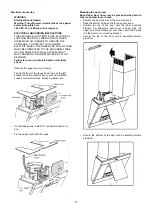
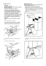
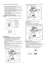
Remove the upper cover (3 screws).
Facing the front of the range hood, remove the left
knockout and the Junction box cover and install the
conduit connector (cULus listed) in junction box.
•
If not already done, install 1/2” conduit connector in j-
box.
•
Fix the upper cover with 3 screws.
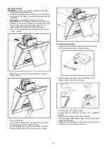
Mounting the duct cover
Note: Upper Duct Cover may be placed upside down to
hide (or unhide) louver holes.
•
Position the duct cover over the mounted hood.
•
Slide the bottom of the duct into the canopy area.
• Position the top of the duct over the duct mounting
bracket. If a telescopic duct cover is used, grab the
upper part of the telescopic duct cover, pull it and place
it in the duct cover mounting bracket.
• Secure the top of the duct with 2 assembly screws
provided.
• Secure the bottom of the duct with 2 assembly screws
provided.
Summary of Contents for EPC632SS
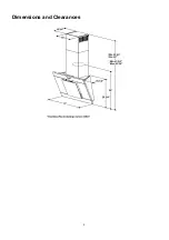
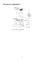
Page 6: ...6 Dimensions and Clearances ...
Page 26: ...26 Dimensions et Dégagement ...


