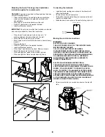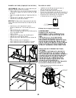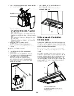
Mounting the hood (This range hood installation
instruction applies for concrete wall)
WARNING
:
2 people are required to lift and position the hood
onto the mounting screws.
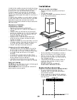
Place the template on the wall along the horizontal line,
make sure the template is leveled and centered with
the centerline.
Mark “upper” screw holes locations in the wall.
Drill 5/16” pilot holes in the marked locations.
Install wall fastener anchors.
IMPORTANT.
Check to be sure that hole locations are leveled
and correctly centered by the vertical centerline.
Drive “upper” wood screws, by hand. Leave ¼ “ of
distance between the screw head and the wall.
Mount the hood onto the “upper” screws.
Mark “lower” wood screw holes locations in the wall using
a pencil.
Remove the hood.
Drill 5/16” pilot holes in the marked locations.
Install wall fastener anchors.
Drive “lower” wood screws, by hand. Remove screws.
Mount the hood onto the “upper” screws.
Drive and tight the “upper” wood screws, by hand.
Drive and tight the “lower” wood screws, by hand.
•
•
•
•
•
•
•
•
•
•
•
•
•
•
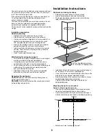
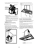
Connecting the ductwork
Install ductwork, making connections in the direction of
airflow as illustrated.
Push duct over the exhaust outlet.
Wrap all duct joints and the flange connections with duct
tape for an airtight seal.
Make the same connection in the wall or ceiling vent exit.
Making the electrical connections
WARNING:
ELECTRICAL SHOCK HAZARD
TURN OFF POWER CIRCUIT AT THE SERVICE PANEL
BEFORE WIRING THIS UNIT.
10 V, 15 OR 0 AMP CIRCUIT REQUIRED.
IF HOUSE WIRING IS NOT A 3 WIRE INSTALLATION
(NEUTRAL, LINE AND GROUND), A GROUND MUST BE
PROVIDED BY THE INSTALLER. WHEN HOUSE WIRING
IS ALUMINUM, BE SURE TO USE U.L. APPROVED
ANTI-OXIDANT COMPOUND AND ALUMINUM-TO-
COPPER CONNECTORS.
ELECTRICAL GROUNDING INSTRUCTIONS
THIS APPLIANCE IS FITTED WITH AN ELECTRICAL
JUNCTION BOX WITH THREE WIRES, THE WIRE COLOR
GREEN / YELLOW SERVES TO GROUND THE APPLI-
ANCE. TO PROTECT YOU AGAINST ELECTRIC SHOCK,
THE GREEN/YELLOW WIRE MUST BE CONNECTED TO
THE GROUNDING WIRE IN YOUR HOME ELECTRICAL
SYSTEM, AND IT MUST UNDER NO CIRCUMSTANCES BE
CUT OR REMOVED. FAILURE TO DO SO CAN RESULT
IN DEATH OR ELECTRICAL SHOCK.
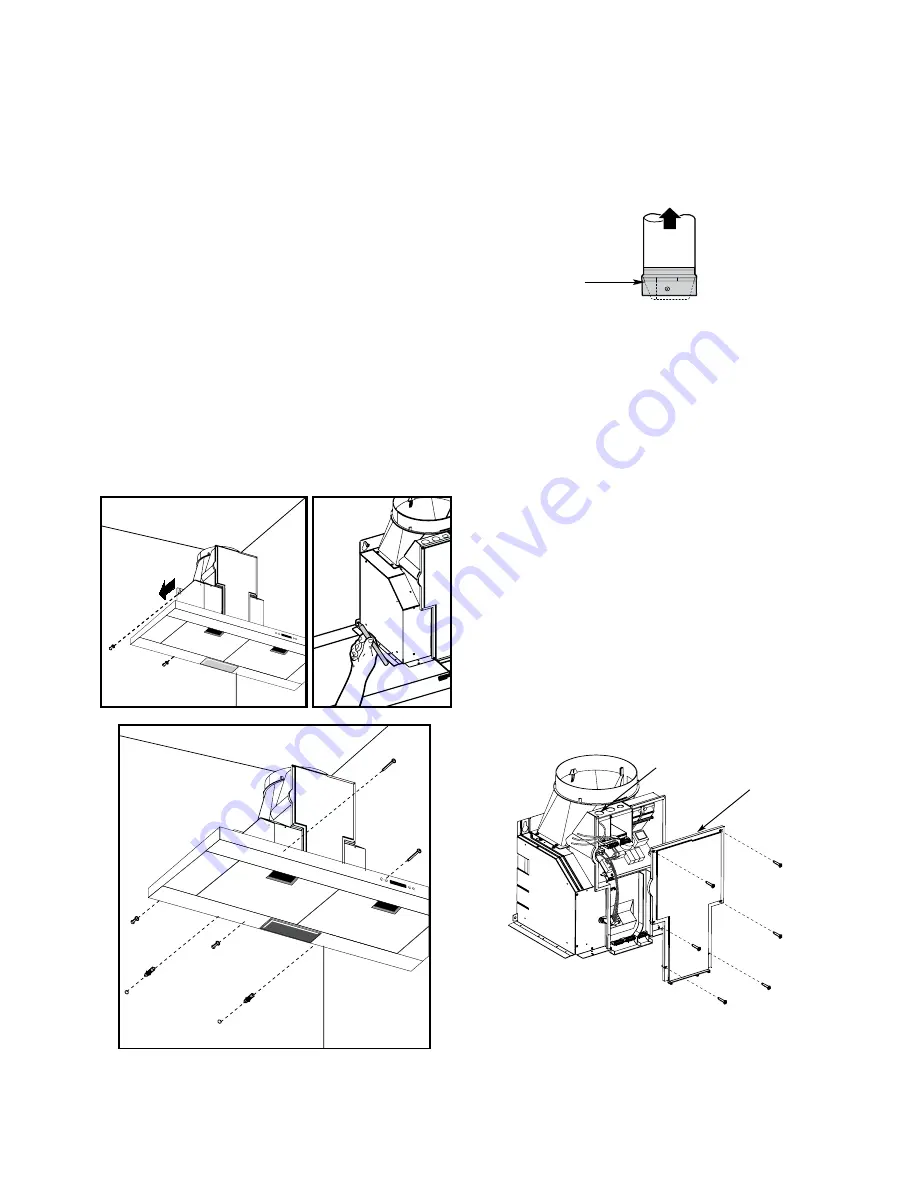
Remove junction box cover and knockout on the top left
side.
•
•
•
•
•
Duct tape
over seam
Air Flow Direction
Knockout
Junction Box
Wall Cover


