27
EN/IEC 61000-3-2; EN/IEC 61000-3-3; ETSI EN 301 489-
1;ETSI EN 301 489-17; ETSI EN 300 328; IEC 62311:2019.
Suggestions for a correct use in order to reduce the
environmental impact: Switch ON the hood at minimum
speed when you start cooking and kept it running for few
minutes after cooking is finished. Increase the speed only in
case of large amount of smoke and vapor and use boost
speed(s) only in extreme situations. Replace the charcoal
filter(s) when necessary to maintain a good odor reduction
efficiency. Clean the grease filter(s) when necessary to
maintain a good grease filter efficiency. Use the maximum
diameter of the ducting system indicated in this manual to
optimize efficiency and minimize noise.
Use
The hood is designed to be used either for exhausting or filter
version.
Extraction version
In this case the fumes are conveyed outside of the building by
means of a special pipe connected with the connection ring
located on top of the hood.
CAUTION
!
The exhausting pipe is not supplied and must be purchased
apart.
Diameter of the exhausting pipe must be equal to that of the
connection ring.
CAUTION
!
If the hood is supplied with active charcoal filter, then it must
be removed.
Filtration version
The aspirated air will be degreased and deodorised before
being fed back into the room.
In order to use the hood in this version, you have to install a
system of additional filtering based on activated charcoal.
Note:
The recycled air in the charcoal filter is sent back to the
kitchen through a duct which conveys air on a side of the
cabinet.
The models with no suction motor only operate in ducting
mode, and must be connected to an external suction device
(not supplied).
The connecting instructions are supplied with the peripheral
suction unit.
Installation
Note:
The installation must be performed so that accessibility
to the hood and its electronic components is always ensured
for possible technical assistance interventions.
Note
: the cable that connects the remote motor to the hood is
3 metres long
Caution! Do not cut the cable between the hood and the
engine to avoid losing your right to warranty!
Mounting
Before starting to mount the appliance, make sure that no
component is damaged, otherwise contact the dealer and stop
mounting. In addition, read all the instructions below carefully.
•
Use an air outlet pipe no longer than 5 metres.
•
Limit the number of curves in the duct since each curve
reduces the suction effectiveness equivalent to 1 linear
metre. (E.g.: if two 90° curves are used, the duct should
be no longer than 3 metres).
•
Avoid drastic changes of direction.
•
Use a duct with 150mm diameter constant for the whole
length.
•
Use a duct made of standard complying material.
•
In case of failure to observe the instructions above, the
supplier can not be held responsible for capacity or noise
problems and no warranty will be granted.
•
Before making the hole, make sure that the inside of the
cabinet, near the hood housing area, does not have the
structure of the cabinet or other particulars which may
cause problems for the proper installation. Make sure
that the overall dimensions of the hood and the hob ae
compatible with the cabinet and therefore the installation
is feasible.
•
Before inserting the screws into the cabinet, make sure
that the product is perfectly perpendicular to the worktop.
Panel Assembly
(only for models where the panel is not supplied with the
hood)
CAUTION
!
Installation must be carried out only by qualified installers.
FOR THE INSTALLER: Responsibility for installation of the
hood, including verification of the conformity of any fixing kit
supplied with the product, is the sole responsibility of the
installer. Following is a non-exhaustive list of helpful
instructions for the installer:
- use a fireproof PANEL (compliant with art. 30 of IEC/EN
60335-2- 31), suitable for the operating temperature (at
least 80°C) and humidity (at least 93%) reached during use;
−
total weight of PANEL used should not exceed 2,5 kg;
−
secure the PANEL to the hood using the fixing points. See
the illustrations dedicated to assembly of the panel not
supplied with the hood.
−
use suitable mechanical parts to fix the PANEL (not
included in the assembly kit). Elica denies all liability for
damage to persons or property resulting from incorrect
installation of the gypsum panels and/or product.
Summary of Contents for GETUP BL MAT/A/90
Page 3: ... M1 M2 a 5 ...
Page 4: ...1 754 862 785 270 2 300 94 303 198 300 110 24 64 82 737 min 749 max ...
Page 5: ... 60 112 850 7 90 90 6 r3 3 A s s P P 864 2 100 ...
Page 6: ... 60 100 850 B P P ø150mm 11 1 11 2 4 3 ...
Page 7: ...5 b FRONT a L 754mm b a a L 64mm L max 20mm M1 M2 ...
Page 8: ...1 2 6 M1 M2 a b ...
Page 9: ...7 M1 M2 3 2X M4x15a 4 ...
Page 10: ...8 M1 M2 ...
Page 11: ...2X ø3 5X9 5 1X ø4 5X16 3X ø3 5X9 5 1X ø4 5X16 2X 90 10 9 2X ...
Page 12: ...11 1 FRONT 8X FRONT FRONT 2 1 ...
Page 13: ...11 2 BACK 8X 8X BACK FRONT BACK 8X 1 2 3 ...
Page 14: ...V Hz 12 13 1 2 3 4 ...
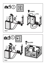
Page 15: ...4X M4X10 4X ø4 5X16 V Hz 14 1 14 2 ...
Page 16: ...15 1 cm2 cm2 Ø 150 mm 16 2 P1 1 2 ...
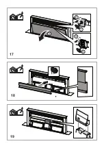
Page 17: ...19 18 17 1 2 3 4 5 ...
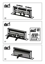
Page 18: ...20 21 23 2x 2x ...
Page 19: ......
Page 189: ...6 21 ...
Page 190: ...5 ...
Page 191: ...4 ...
Page 192: ...3 2 5 ...
Page 193: ...2 ...
Page 194: ...1 ...
Page 195: ......
Page 196: ...LIB0163215 Ed 10 20 ...


