background image

Rev.041014-JA   


www.elitescreens.com 


ezFrame Plus Series 

Fixed   Frame   Projection   Screen


User’s   Guide   


Hardware and Parts List


1. Frame Parts 

x 6 pcs (4 top/bottom horizontal frame pcs + 2 side vertical frame pcs)


2. Tension Rods 

x 6 pcs (4 top/bottom rods + 2 side rods) 

3. Screen Material 

x 1 pc 

4. Center joints 

x 2 pcs 

5. Elbow Joints 

x 4 pcs 

6. Wall brackets 

x 2 – 3 pcs (depending on model/size) 

7. M5x50 wood screws        x 6 pcs 
8. Hollow wall anchor         x 6 pcs 
9. M5x15 screws    x 16 pcs 
10. Center Support Bar          x 1 – 2 pcs (depending on model/size) 
11. Support joiner                  x 2 – 4 pcs (depending on model/size) 
12. Fix Plates 

  x 60 – 180 pcs (depending on model/size) 

Note: Please make sure all parts are included in your package before proceeding to assemble your Elite 
Screens fixed frame projection screen. 


FRAME ASSEMBLY


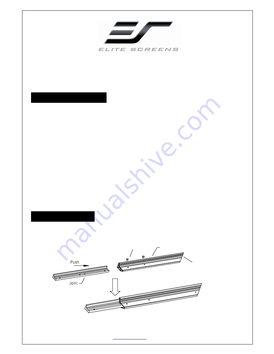
1. Insert the 

center joint

 connector into to one of the 1/2 horizontal frames and fasten it with two 

M5x15 screws

.


bevel connection 
 

½

 Horizontal Frame 

M5

×

15 screws 


Summary of Contents for ezFrame Plus Series

Page 1: ...n model size 7 M5x50 wood screws x 6 pcs 8 Hollow wall anchor x 6 pcs 9 M5x15 screws x 16 pcs 10 Center Support Bar x 1 2 pcs depending on model size 11 Support joiner x 2 4 pcs depending on model siz...

Page 2: ...ould be assembled for a screen b Do not tighten the screws completely until all frame pieces have been assembled correctly 3 Insert both elbow joint connectors into the long horizontal frame and then...

Page 3: ...together following the steps shown below Fig 2 Note When assembled please push simultaneously the two ends of the long frames Attaching the screen material to the frame 1 Unroll the screen material a...

Page 4: ...e four corners in the following order A B C D Fig 4 2 Insert the fix plates as shown on Fig 5 Fix plate is approximately 10 cm away from the frame s corner and fix plate is approximately 5cm away 3 St...

Page 5: ...y put the next set of fix plates 4 as shown in Fig 11 8 Repeat steps 5 7 to for the rest of the sides to complete attaching the screen material Fig 12 Interval markings reveal the best points for inse...

Page 6: ...ith a stud finder recommended and mark the drill hole area of where the screen is to be installed 2 Drill a hole with the proper bit size according to the wood screws included 3 Line up the wall brack...

Page 7: ...e improvement specialist for the best advice on installation 3 Frame parts are made of high quality velour surfaced aluminum and should be handled with care 4 When not in use cover over the screen wit...

Reviews: