background image

MZ04242018 


www.elitescreens.com


WARNING


Individual modifications to this product are prohibited and will void the manufacturer’s warranty. Please 
contact the Elite Screens Customer Service Team with any questions. 
 

NOTE

This equipment has been tested and found to comply with the limits for a Class B digital device, pursuant to 
Part 15 of the FCC Rules. 
 
The product settings are designed to provide reasonable protection against any radio interference within a 
residential installation. If properly installed, the Evanesce Tab-Tension screen may suffer from RF 
interference from other home electronics.   
 
Although radio interference affecting other household electronics is unlikely, the following steps can be 
taken should RF interference occur. 


Reorient or relocate the receiving antenna on the device that may be casing the interference. 


Increase the distance between the screen and the interfering device’s receiver. 


Connect the projection screen to another power source apart from the interfering device. 


Pre-Installation 

1.


Carefully unpack the screen. 

2.


Always handle the screen upright on a level, clean surface. 

3.


Keep the screen out of contact with foreign particles such as dust, sawdust, and/or liquids. 

NOTE


Regardless of the mounting method, the screen should be securely supported so that the vibration or     
pulling on the viewing surface will not cause the casing to become loose or fall. Included mounting screws 
are complimentary and may not be appropriate for all mounting surfaces. Use appropriate anchors to safely 
secure the screen to the mounting surface or consult with a professional installer. 
 

A. Wall/Ceiling mount 

bracket x2 

B. M5x60 Screw x6 

C. M12 Dry-wall anchor x6 

D.Bracket connector x2 

(Installed on the housing) 


E. M5x11 Bolt Screw x4 

(Screw on the D parts) 

F. M5x25MM round head 

cross screws x2 

G. M5x30MM eyebolt screw 

& M5 nut x2 

H. Snap link x2 


Summary of Contents for Saker Series

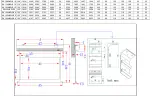
Page 1: ...70 2040 610 60 100 102 108 35 23 SK120XHW E10 120 16 9 2955 2657 2155 2757 50 2837 1916 1494 1808 254 60 100 102 108 35 23 SK120XHW E20 120 16 9 2955 2657 2155 2757 50 2837 2170 1494 2062 508 60 100 1...

Page 2: ...3 2685 50 2765 2088 1615 1980 305 60 100 102 108 35 23 SK135NXW E6 135 16 10 3198 2908 2398 3008 50 3088 2154 1817 2029 152 60 118 118 125 35 23 SK150NXW2 E6 150 16 10 3521 3231 2721 3331 50 3411 2356...

Page 3: ...avoid electrical shock or product damage do not install this device in a damp place Do not place any heavy objects over the power cord Position the power cord properly to avoid creating a trip hazard...

Page 4: ...ference Increase the distance between the screen and the interfering device s receiver Connect the projection screen to another power source apart from the interfering device Pre Installation 1 Carefu...

Page 5: ...additional support for the screen Two or more people are required while one holds the screen in place B Ceiling Mount I Ceiling Mount movable position This mount method allows the screen to slide hor...

Page 6: ...ge 1 After ensuring the power outlet screen are compatible voltage plug the power cord into the power outlet 2 Once the screen has power you ll be able to control it using any of the 6 methods describ...

Page 7: ...ts to your projector s trigger output via a separate cable that may or may not be provided by the manufacturer of the projector The trigger feature will not work without an output cable from the proje...

Page 8: ...Wait 5 seconds and then release the UP button Step 7 Your 5 12V wireless trigger should now be activated with your screen and ready to be used and able to control your screen with your projector s pow...

Page 9: ...ry and get more out of your standard black masking drop Please contact Elite Screens before making any adjustments Tools required A 5 32 allen wrench is needed to adjust the limit screws Screen Limit...

Page 10: ...the way up and drop the screen again to see the difference in the adjustment Increasing the length of the top black drop should be made only if there is no top black drop showing when fully deployed P...

Page 11: ...ill cause permanent damage to the motor s gears To adjust the rise for this instance instead of turning the allen wrench counter clock wise turn it clock wise about ten full circles at a time When mak...

Reviews: