background image

12052022JA 


www.elitescreens.com 


Please use the following installation instructions to obtain superior optical performance from the CineGrey 3D 
Angular Reflective ALR 

(Ambient Light Rejecting)

 Screen 

 
Make sure to follow these instructions in order for the CineGrey 3D to perform correctly. 

A.


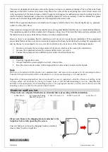
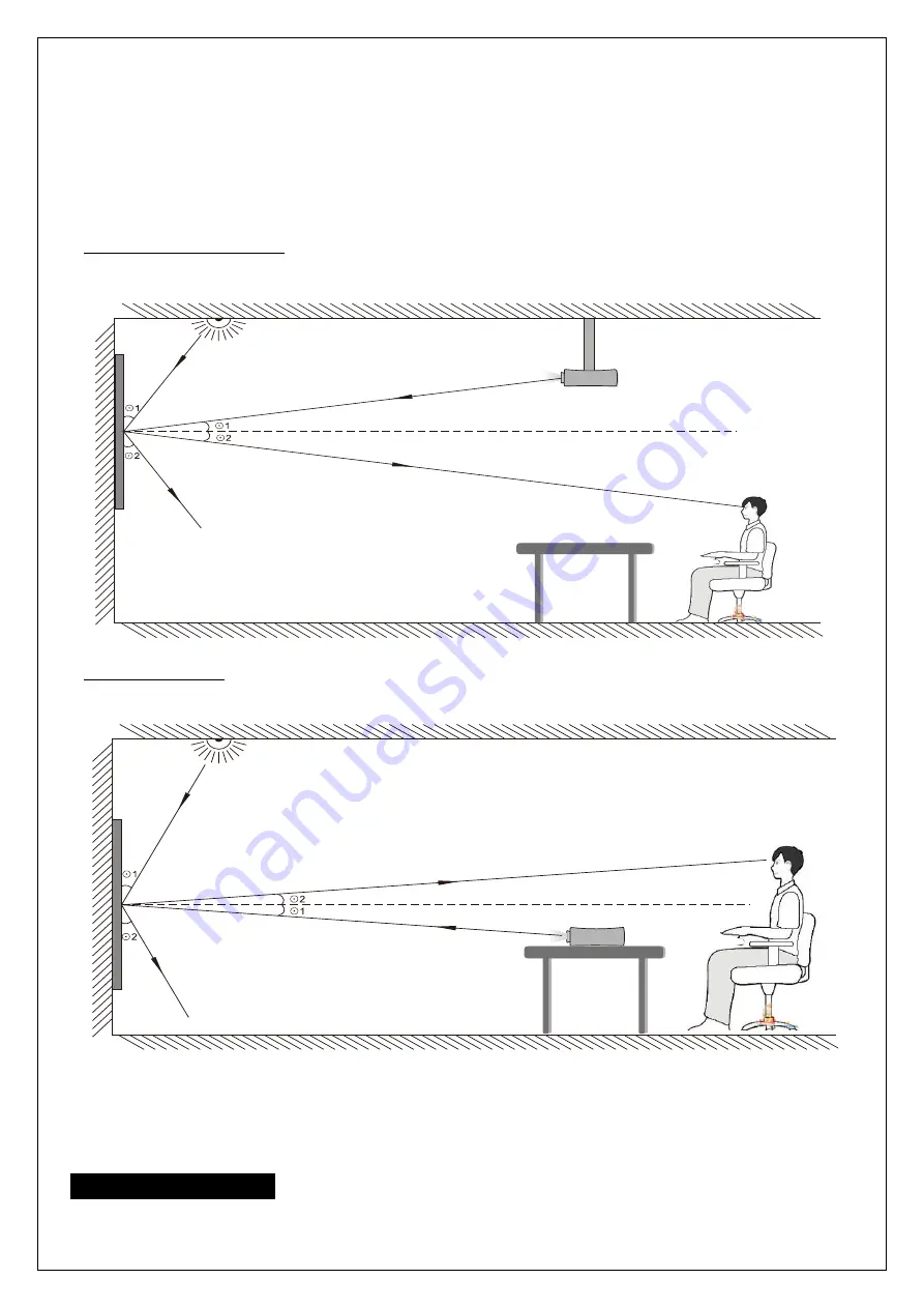
Ambient Light must not come from the same direction as the projector’s light


B.


Minimum Lens Throw Ratio of 1.5x image width 


C.


Not compatible with ultra-short and short-throw projectors


Projector Ceiling Installation

:  Make sure the projector (

light in

) is angled 

(

ϴ

1) 

to reflect 

(

ϴ

2) 

at the mirror-

opposite angle (

light out

) to align w

ith the viewer’s eye level.


Projector Tabletop: 

Make sure the projector (light in) is angled 

(

ϴ

1)

 to reflect 

(

ϴ

2)

 at the mirror-opposite angle 

(light out) to align with the viewer’s eye level.


Images are not up to scale and are for illustrations purposes only

 
Note

: Improper installation will result in light loss and produce a dark image.  This is due to the projector’s light 

reflecting in the wrong direction. 


Installation Instructions 

For installation assistance, please consult a professional Installer. Elite Screens is not liable for faulty installations. 

Summary of Contents for Spectrum Tab-Tension 2 CineGrey 3D Series

Page 1: ...uide for future reference To avoid damaging the unit do not use with any accessories triggering sources not recommended or specified by the manufacturer Handle the unit carefully during transportation...

Page 2: ...r more of the following measures Reorient or relocate the receiving antenna of the device which may be causing the interference Increase the separation between the screen and the device s receiver Con...

Page 3: ...jector Ceiling Installation Make sure the projector light in is angled 1 to reflect 2 at the mirror opposite angle light out to align with the viewer s eye level Projector Tabletop Make sure the proje...

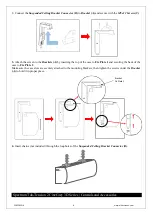
Page 4: ...Then loosen the screw under the Bracket A by turning it counterclockwise 3 Attach the screen to the Brackets A by inserting the top of the case to Fix Plate 1 and securing the back of the case to Fix...

Page 5: ...oosen the screw under the Bracket A by turning it counterclockwise 3 Attach the screen to the Bracket A by inserting the top of the case to Fix Plate 1 and securing the back of the case to Fix Plate 2...

Page 6: ...he case to Fix Plate 1 and securing the back of the case to Fix Plate 2 Make sure the case slots are securely attached to the mounting brackets then tighten the screws under the Bracket A to hold it i...

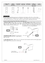
Page 7: ...e control Item A Fig 1 The Infrared functions by direct line of sight contact using a beam range of 30 feet Aim the IR remote at the circular window located on the left side of the screen 2 RF Remote...

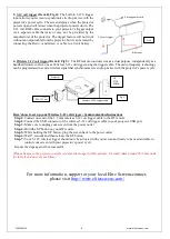
Page 8: ...tor s power cycle Here s how to set up your Wireless 5 12 volt trigger Synchronization Instructions Step1 Connect one end of the 3 5 mm wireless 5 12 volt trigger cable to the RF remote Step 2 Connect...

Reviews: