Page 27 of 130
Doc No.
:
T202001006
6.3 Workspace of the Robot
6.3.1 Mechanical dimensions of the robot
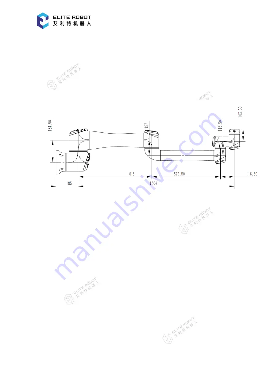
The mechanical dimensions diagram of the EC612 robot is shown in Figure 6-1. The range of
motion of the robot must be considered during installation, as to prevent the surrounding personnel
and equipment from being bumped.
Figure 6-1 Mechanical dimensions diagram of the EC612 robot, with unit of mm
6.3.2 Range of motion of the robot
Figure 6-2 shows the range of motion of the EC612, namely, a sphere with a radius of 1304mm
except the cylindrical space directly above and directly below the base. When choosing the
installation position of the robot, the cylindrical space directly above and directly below the robot
must be considered, as to avoid the tool from being moved toward the cylindrical space as far as
possible. In addition, the rotation angle of the joints 1~6 is -360º
to +360 º
in practical application.


