


Upload (UL)
: The upload function reads
the instrument parameters and writes
them onto the Copy card
Download(dL)
: The download function
writes the parameter map that is on the
copy card at that time onto the
instrument memory.
NOTE:
Upload = instrument—-> Copy card
Download = Copy card —> instrument
The operations are performed by
accessing the folder with the ‘FPr’ label
and selecting the ‘UL’, ’dL’ or ‘Fr’
commands. The operation is confirmed
by pressing the ‘set’ button. If the
operation is successful, a “y” is displayed
whereas if it is unsuccessful an “n” will
be displayed.
Formatting the copy card
This function is necessary when using the
copy card for uploading for the first
time or when using the copy card on
device models that are not compatible.
NOTE: formatting deletes all the data
on the Copy card and cannot be
undone.
Download from reset
Once the copy card has been connected
the instrument is switched on. When the
lamp test is over, one of the following
two labels will be displayed for 5
seconds:
- dLY if the operation is successful
- label DLn if operation fails The display
will then go into default position (probe
or set point).
NOTE: after downloading, the
instrument will begin to work with
the new parameter map that has just
been downloaded.
ADVANCED FUNCTIONS
DOOR SWITCH INPUT
This is a clean contact digital input with
programmable polarity. The door switch
input functions are controlled by the
values of the following parameters:
Parameter H11 is used to configure the
door switch input with values between
-8 and +8. Positive and negative values
are present in order to select the
polarity assigned to the input and:
NOTE: the sign “-” indicates that the
input is activated when the contact is
closed.
The ‘+’ sign indicates that the input is
activated when the contact is open
LIGHT CONTROLLER
Controls the light relay. The function can
be started in two different ways. If you
press the light button the light relay is
switched on if it was off and is switched
off if it was on.
The light status is recorded by the
device as soon as the button is pressed
so that when power is restored after a
black-out the device can continue to
operate in the same way as before the
power failure.
The following parameters control how
the light works:
The configuration of these parameters
controls the status of the light relay by
using the digital input as well as the
normal button.
The parameter dSd automatically
switches on the light relay when the
digital input is enabled and switches it
off when the digital input is disabled
following the delay set by parameter dLt.
Parameter H06 activates the light button
and enables the relay when the door is
open even when the instrument is
powered but is ‘off’.
The dedicated button always deactivates
the light relay even if the digital input is
on or during the dLt delay only if the
parameter OFL=Y.
DIAGNOSTICS
PROBE ALARMS
When one of the probes is outside the
nominal operating range or the probe is
open or has shorted, an alarm is
generated if at least one of these
conditions persists for at least 10
seconds.
If at least one of these 3 alarms is
signalled the alarm LED and relay are
enabled. When activated code E1
appears on the display.
If several alarms are activated at the
same time, they are displayed alternately
for 2 seconds each. An error condition
in the room probe leads to:
- E1 code appears on display
- activation of compressor as indicated
by Ont and OFt
- deactivation of maximum and
minimum alarm controller.
MINIMUM AND MAXIMUM
TEMPERATURE
ALARM
The alarm is regulated on the room
probe. The temperature limits are
defined by parameters HAL and LAL. The
limits refer to the set point if parameter
Att=1 and are absolute if Att=0.
NOTE: If the alarms are relative, the
parameter HA1 is set to positive
values and LA1 to negative values.
ALARM WITH THRESHOLD REFERRING
TO PROBE 3
An alarm is associated with probe 3 that
refers to a threshold that is reset at a
specified differential.
By setting parameter PbA=3 probe 3 will
signal a high or low temperature alarm
for exceeding the set value.
The alarm is handled in the same way as
the other temperature alarms and
standard signal delays are used.
EXTERNAL ALARM
It is set if the digital input is enabled
with the delay specified by parameter
dAd and remains enabled until the next
time the digital input is deactivated. The
alarm consists of an alarm LED that
remains on, activation of a buzzer and
deactivation of all the device loads (if
specified by the EAL parameter).
If an external alarm is present the EA
label is displayed in the AL folder.
It is reset the next time the digital input
is deactivated and the buzzer can be
manually silenced.
Par
Description
dOd
Digital input switches off loads
dAd
D.I. activation delay
OAO
Alarm signal delay after dis-
disabling the digital input (door closed)
tdO
Time out door open. Time out
signal after activation of D.I.
(door open)
H11
Digital output configurability/polarity 1
H21...H25
Digital output configurability 1...5
Par
Description
H06
Button/aux input/door switch light active
when instrument off
dSd
Enabling light relay by door switch
dLt
Delay Light Relay
deactivation delay
OFL
Light switch always disables light relay
OAO
Alarm signal delay after
disabling the digital input
(door closed)
tdO
Time out door open.
Time out signal after activation of D.I.
(door open)
H11
Digital output configurability/polarity 1
H21...H25
Digital output configurability 1...5
Signal
Description
E1
Faulty room probe
E3
Faulty display probe
EWDR 981
2/8
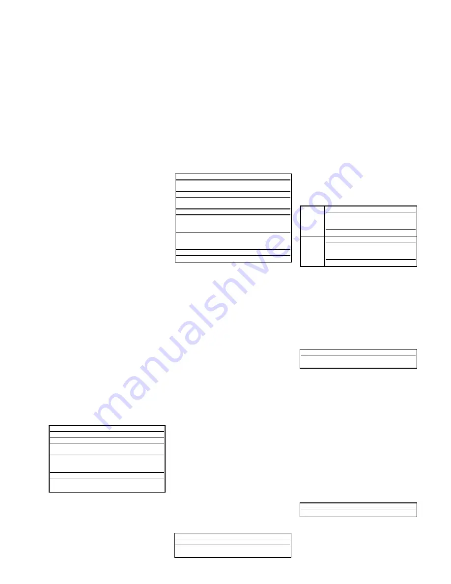
Att=0
absolute
Maximum temperature alarm
room probe temperature
≥
HAL
Minimum temperature alarm
room probe temperature
≤
LAL
Att=1
relative
Maximum temperature alarm
room probe temperature
≥
Set + HAL
Minimum temperature alarm room
probe temperature
≤
Set + LAL
Signal
Description
AH3
High temperature alarm
AL3
Low temperature alarm
Signal
Description
EA
External alarm


