


CP
dEF
AL
level 1 par
level 1 par
level 1 par
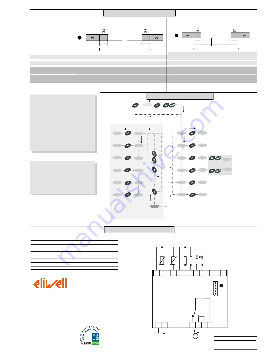
PA1›0
set PA1 value
diS
CnF
Fpr
level 1 par
level 1 par
level 1 par
level 2 par
level 2 par
level 2 par
level 2 par
level 2 par
CP
dEF
diS
CnF
PA2›0
set PA2 value
level 2
level 1
change
par value
scroll
parameters
press for 5 sec
level 2 par
Lit
AL
PA2
PROGRAMMING MENU
EWDR 981
8/8
The technical characteristics in this
document concerning measurements (range,
accuracy, resolution, etc.) refer to the
instrument in the strictest sense and not to
any accessories provided such as probes,
for example. This means that an error
introduced by the probe is added to any
error that is in the instrument.
Minimum temperature alarm
Maximum temperature alarm
LAL
AFd
HAL
AFd
1
set+ LAL
AFd
Off
set+HAL
AFd
set
2
Temperature lower than or equal to LAL (LAL with sign)
Temperature lower than or equal to set point+LAL (set-|LAL|)
(LAL only negative)
Temperature higher than or equal to HAL (HAL with sign)
Maximum temperature alarm
back swing
Minimum temperature alarm
back swing
Temperature higher than or equal to LAL+AFd
Temperature lower than or equal to HAL-AFd
Temperature expressed as an absolute value (par “Att0)
Abs(olute)
Temperature expressed in relation to set point
(par “Att”=0) reL(ative)
if Att=reL(ative) LAL must be negative: therefore set
point+LAL<set point because set point+(-|LAL|)=set point-|LAL|
MIN/MAX ALARM MENU
WIRING DIAGRAM
TERMINALS
1-2
Probe input 1 (room probe)
1-4
Probe input 3 (display or 2nd evaporator probe)
5-6
Digital input 1
5-7
Digital input 2
8-9
Auxiliary output 12V
c
/20mA (E) see par. H25
(alarm default)
13-14
Power supply 230V
a
A
TTL input for Copy Card
20-21-22* N.O. relay output (C) see par. H21 (compressor default)
19-22*
N.C. relay output (C) see par. H21 (compressor default)
EWDR 981
1 2
4 5 6 7
8 9
10 11 12
13 14
19 20 21 22
TTL
A
(C)
AUX OUT
12V
C
/20mA
P
o
w
e
r
S
u
p
p
ly
Pb1
Pb3
D
.I.1
D
.I.2
(E)
Eliwell & Controlli s.r.l.
Via dell'Industria, 15 Zona Industriale Paludi
32010 Pieve d'Alpago (BL) ITALY
Tel39 0437 986111
Fac39 0437 989066
Internet http://www.eliwell.it
Technical Customer Support:
Email: techsuppeliwell@invensys.com
Tel39 0437 986300
Climate Controls Europe
An Invensys Company
3/05 eng
cod. 9IS43091
* Relay characteristics
Relay output (C) 16A 1hP 250V
a
DISCLAIMER
This document is the exclusive property of
Eliwell and cannot be reproduced and
circulated unless expressly authorized by
Eliwell.
Although Eliwell has taken all possible
measures to guarantee the accuracy of this
document, it declines any responsibility for any
damage arising out of its use.
The same applies to any person or company
involved in preparing and writing this
document. Eliwell reserves the right to make
any changes or improvements without prior
notice and at any time.
Temperature higher than or equal to set point+HAL (HAL only positive)
Temperature higher than or equal to set point + LAL + AFd
set point -|LAL|+AFd
Temperature lower than or equal to set point+HAL-AFd


