background image

USER INTERFACE

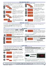
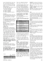
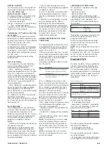
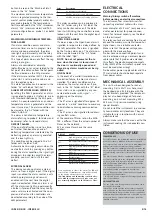
The user has a display and four buttons
for controlling instrument status and pro-
gramming. The device can also be con-
nected to a remote display.

At start-up the instrument performs a
Lamp Test; the display and LEDs flash for a
few seconds to check that they are work-
ing correctly. The instrument has two main
menus: the Machine Status menu and the
Programming menu.

ACCESSING AND USING MENUS

The resources are arranged in a menu that
can be accessed by pressing and quickly
releasing the “set” button (Machine Status
menu) or holding down the “set” button
for more than 5 seconds (Programming
menu). To access the contents of each
folder indicated by the relevant label, just
press the “set” button once. 
You can now scroll through the contents
of each folder, modify it or use its func-
tions. 
If you do not use the keyboard for over 15
seconds (time-out) or if you press the
“fnc” button once, the last value shown on
the display is confirmed and you are taken
back to the previous screen mask.

REMOTE DISPLAY

This has a display with 3   sign that
displays the parameter programming and
alarm display values on the controller it is
connected to during probe reading.

MACHINE STATUS MENU
(See Machine Status Menu Diagram)

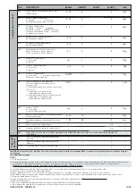
Position

Associated function

Status

Set point/Reduced set point ON for parameter programming level 2

blinking when reduced set point is entered
(set point ON for setting set point)

Compressor or relay 1

ON for compressor on; blinking 
for protection delay or enabling blocked

Defrosting

ON when defrosting in progress; blinking when activated
manually or by digital input

Alarm

ON for active alarm; blinking for silenced alarm

Fans

ON when fan is on

aux

ON when auxiliary output is operating

aux

fnc

set

ID985/E LX

aux

set

fnc

UP button

Scrolls through the menu items

Increases values

Activates manual defrosting

(see H31 parameter)

DOWN button

Scrolls through the menu items

Decreases the values

Parameter programmable

(see H32 parameter)

fnc button

ESC function (quit)
Parameter programmable
(see H33 parameter

Set button

Accesses Set point and rtc folder
Accesses the Menus
Confirms the commands
Displays the alarms (if active)
Stores hours/min

cod. 9IS23080

rel. 4/08 -GB-

ID 985/S/E/CK - ID985/E LX

electronic controllers for “ventilated” refrigeration units 

w

w

w

w

ii

ii

tt

tt

h

h

h

h


R

R

R

R

S

S

S

S

4

4

4

4

8

8

8

8

5

5

5

5


o

o

o

o

n

n

n

n


b

b

b

b

o

o

o

o

a

a

a

a

rr

rr

d

d

d

d


((

((

II

II

D

D

D

D

9

9

9

9

8

8

8

8

5

5

5

5

//

//

S

S

S

S

//

//

E

E

E

E

//

//

C

C

C

C

K

K

K

K

))

))


a

a

a

a

n

n

n

n

d

d

d

d


rr

rr

e

e

e

e

m

m

m

m

o

o

o

o

tt

tt

e

e

e

e


d

d

d

d

ii

ii

ss

ss

p

p

p

p

ll

ll

a

a

a

a

y

y

y

y

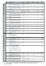
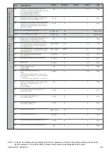
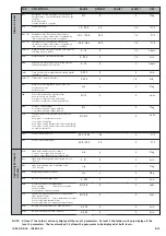
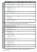
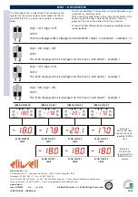
BUTTONS AND DISPLAY

if alarm(s)

 present

AL

Pb1

Pb2

SEt

set

alarms

Pb1 value 

Pb2 value 

SEt value

set

set

set

set

change SEt

value

show alarms

if present

press and release

(single press)

Pb3

Pb3 value 

set

if present

rtc

set

h00

d00

'00

2 sec

2 sec

set 

hours

set 

days

set 

minutes

se presente

d00= Sunday

MACHINE STATUS MENU DIAGRAM

LEDS

Summary of Contents for ID 985

Page 1: ...t point is entered set point ON for setting set point Compressor or relay 1 ON for compressor on blinking for protection delay or enabling blocked Defrosting ON when defrosting in progress blinking when activated manually or by digital input Alarm ON for active alarm blinking for silenced alarm Fans ON when fan is on aux ON when auxiliary output is operating aux fnc set ID985 E LX aux set fnc UP b...

Page 2: ...ed if it is not successful n will be displayed Download from reset Connect the copy card when the instrument is OFF The program ming parameters are downloaded when the device is switched on At the end of the lamp test the following messages are dis played for about 5 seconds dLY label if copy operation is successful DLn label if operation fails NOTE after the parameters have been downloaded the de...

Page 3: ...hen it is on stand by according to the following parameters The Stand by controller can be digital input or button enabled if suitably configured The status of the instrument when on stand by is determined by the value of parameter H08 Three possible operating modes are defined EXAMPLE 1 the display is off and the con trollers active the instrument signals any alarms by reactivating the display OF...

Page 4: ...r loads are immediately deactivated the alarm LED lights up to signal tripping and the label nPA in the alarm folder appears on the display Controlling is performed using 2 parame ters PEn and PEI nPA is a subfolder of AL Alarms and keeps a record of each time the pressure switch is activated if the value indicated by PEn is reached in a period of time that is less than or equal to PEI the label n...

Page 5: ...so signalled for address ing conflicts when a the number of Slaves set on the MAS TER is different from the actual number of Slaves on the network b 2 or more Slaves have the same address ELECTRICAL CONNECTIONS Warning Always switch off machine before working on electrical connections The instrument has screw terminals for connecting electrical cables with a maxi mum diameter of 2 5 mm2 only one c...

Page 6: ... or after a power failure Not active if 0 0 250 0 1 2 min dty Defrost type 0 Electrical or Off Cycle defrost Compressor OFF during Defrost 1 Reverse cycle defrost hot gas Compressor On during Defrost 2 Free Independent defrost compressor cycles ON OFF according to temperature during defrost 0 1 2 0 1 2 flag dit Period of time elapsing between the start of two defrosts 0 function disabled 0 250 6 1...

Page 7: ...y all the level 1 parameters At level 2 the folders will only display all the level 2 parameters The level marked 1 2 allows the parameter to be displayed at both levels FAd Fan activation intervention differential see FSt Fot 1 0 50 0 2 0 1 2 C F Fdt Delay before fan activation after defrosting 0 250 0 1 2 min dt Dripping time 0 250 0 1 2 min FCO Disables fans with compressor off Off y fans activ...

Page 8: ...f disabling delay dLt is active n y n 2 flag dAd Delay in enabling digital input 0 255 0 2 min dOd Digital input switches off loads n y n 2 flag Att Determines if LAL and HAL are expressed as absolute values or as a differential related to the set point 0 absolute value 1 value related to set point 0 1 0 2 flag AFd Alarm differential 1 0 50 0 2 0 1 2 C F HAL 4 Maximum alarm Temperature limit whose...

Page 9: ...lag L04 Refers to Slave only Distributed display n Slave displays local values y Slave displays Master display n y y 2 Flag L05 Activation of Master network functions n does not ask Slaves for activation of remote functions y asks Slaves for activation of remote functions Slave n ignores activation of remote functions from Master y accepts activation of remote functions from Master n y n 2 Flag L0...

Page 10: ...d by operating mode 0 only display switched off 1 display on and controls locked 2 display off and controls locked 0 1 2 2 2 num H12 6 Configuration of digital inputs polarity Same as H11 9 9 0 2 num Configuration CnF label H02 Quick activation time for functions with configured buttons Not possible for aux time expected 1 second 0 15 5 2 sec H06 Button input aux door switch light active when inst...

Page 11: ...eter 1 2 1 2 Copy Card Fpr label UL Transfer of parameter map from instrument to Copy Card dL Transfer of parameter map from Copy Card to instrument 1 1 Fr 8 Formatting Cancels all data in the Copy Card 1 NOTES 1 See Duty Cycle page 4 3 If relative values are present par Att 1 parameter HAL is set to positive values and the parameter LAL is set to negative values LAL 4 Refers exclusively to high a...

Page 12: ...oduced by the probe is added to any error that is characteristic of the instrument RS485 RS485 Personal Computer PCI1110 1120 TelevisCompact TelevisStation RS485 BusAdapter TTL Personal Computer PCI1110 1120 TelevisCompact TelevisStation BusAdapter130 150 TTL RS 485 serial interface on DIN rail for connecting the device and an RS 485 network designed for connection to Televis or ModBUS supervision...

Page 13: ... 5 2 A 1 4 hp 250Va B C D SPST 3A 250Va A SPDT 8 3 A 1 2 hp 250Va B C SPST 8 3 A 1 2 hp 250Va D SPST 5 2 A 1 4 hp 250Va if present from 55 to 140 C better than 0 5 of bottom scale 1 digit 1 or 0 1 C 2 5W 3VA 12 24Va 12 36Vc 10 or 95 240Va 10 12Va 10 50 60 Hz from instrument it is connected to 1 2 3 4 5 6 7 8 9 10 14 15 16 17 18 19 20 A B C D LINK POWER SUPPLY TTL ECHO GND RS 485 LINK Pb2 Pb1 Pb3 D...

Page 14: ...VE 1 L00 0 ECHO SLAVE 2 L00 0 ECHO SLAVE 3 L00 0 code 9IS23080 GB rel 4 08 Eliwell Controls s r l 2008 All rights reserved Eliwell Controls s r l Via dell Industria 15 Zona Industriale Paludi 32010 Pieve d Alpago BL ITALY Telephone 39 0437 986 111 Fax 39 0437 989 066 Sales 39 0437 986 100 Italy 39 0437 986 200 other countries E mail saleseliwell invensyscontrols com Technical helpline 39 0437 986 ...

Reviews: