ID 985/S/E/CK - ID985/E LX
11/14
PAR.
DESCRIPTION
RANGE
DEFAULT
VALUE*
LEVEL**
U.M.
Configuration- CnF label
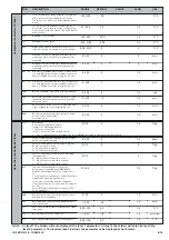
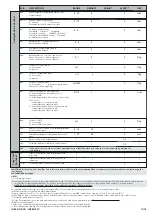
H24
Digital output D configurability Same as H21
(default alarm)
0...10
4
2
num
H25 (7)
BUZZER output configurability
0= disabled
1...7= not used
8=enabled (default) if buzzer is present
0...10
8
2
num
H31
UP button configurability
0=disabled 1=defrost 2=auxiliary
3=reduced set point 4=HACCP alarm reset
5=disables alarm HACCP 6=light
7=stand-by
8= maintenance request
H32
DOWN button configurability Same as
H31(0=disabled default)
0...8
0
2
num
H33
ESC button configurability Same as
H31(0=disabled default)
0...8
0
2
num
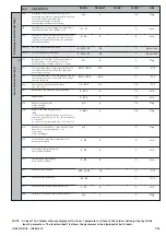
0...8
1
2
num
H40
Enabling inversion of probe 1 and probe 2
0=Pb1 on channel 1, Pb2 on channel 2
1=Pb1 on channel 2, Pb2 on channel 1
0...1
0
2
Flag
H41
Presence of control probe:
n= not present
y= present
n/y
y
2
flag
H42
Presence of evaporator probe:
n= not present;
y= present
n/y
y
2
flag
H43
Presence of display probe:
n= not present
y= present (display probe)
2EP= probe on 2nd evaporator
n/y/2EP
n
2
flag
H45
Start of defrosting for dual evaporator:
0= defrost activated if temperature of 1st
evaporator<dSt
1= defrosting activated if at least one of the condi-
tions is met:
-temperature 1st evaporator<dSt
-temperature 2nd evaporator<dS2
2= defrosting activated if both conditions are met:
-temperature 1st evaporator<dSt
-temperature 2nd evaporator<dS2
0/1/2
1
2
num
H48
Presence of RTC
n= not present;
y= present (Real Time Clock)
n/y
y
2
flag
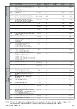
PA2
in the CnF folder you can access level 2 parameters from label PA2 when you enter the correct password by pressing the
“set” button
reL
Device version. Read only parameter
tAb
Parameter table; Reserved; Read only parameter
/
/
1-2
/
/
/
1-2
/
Copy Card
Fpr label
UL
Transfer of parameter map from instrument to
Copy Card
dL
Transfer of parameter map from Copy Card to
instrument
/
/
1
/
/
/
1
/
Fr (8)
Formatting. Cancels all data in the Copy Card
/
/
1
/
NOTES:
(1) See Duty Cycle page 4
(3) If relative values are present (par. Att=1) parameter HAL is set to positive values and the parameter LAL is set to negative values (-LAL)
(4) Refers exclusively to high and low temperature alarms
(5) when changing from °C to °F or vice versa the set points, differentials, etc. are NOT converted (for example, “set=10 °C becomes set=10°F”)
(6) CAUTION: positive or negative values change polarity, Positive values: active input when contact is closed; Negative values: active input when contact is open.
(7) Parameter visible if buzzer is present.
(8) If the Fpr parameter is used, the data previously stored on the Copy Card will be permanently lost.
This operation cannot be undone
(9) Only for Modbus models
* Value: to be compiled manually by user with any custom settings (if different from default settings)
** Level: indicates the visibility level of parameters accessed using a password (see relevant paragraph)
(2) In the deF folder there are two folders: “dd” (daily defrost) and “Fd” (festive defrost); the first folder includes the parameters dE1...dE8 (start of daily defrost) and the
second folder includes the parameters F1...F8 (start of festive defrost). The two folders can only be seen if parameter dCt=3 and RTC is declared present.
NOTE: Do not confuse the days d0...d6 related to the nAd folder with dE1...dE8 daily defrost.
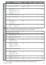
FUNCTIONS (folder with “FnC” label)The FnC folder (last folder visible from the Programming Menu) contains several functions that are activated using the
“set” button
SEE FUNCTIONS paragraph
PEn
Number of errors allowed per maximum/minimum
pressure switch input
0...15
10
2
num
PEI
Minimum/maximum pressure switch error count
time
1...99
60
2
min


