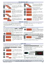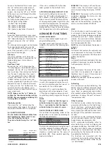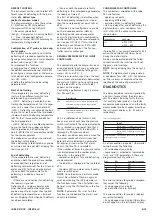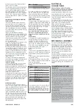
ID 985/S/E/CK - ID985/E LX
13/14
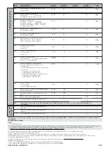
TECHNICAL DATA
ID 985/S/E/CK - ID 985/E LX - ECHO
Front protection
Casing
Dimensions ID985/S/E/CK - ID985/E LX
Dimensions ECHO
Mounting ID985/S/E/CK - ID985/E LX
Mounting ECHO
Operating temperature
Storage temperature
Usage ambient humidity
Storage ambient humidity
Display range
Analogue inputs
Digital inputs
Serial ID985/S/E/CK - ID985/E LX
Serial ID985/E LX
Serial ECHO
Digital outputs
ID985/S/E/CK
ID985/E LX
Buzzer
Measurement range
Accuracy
Resolution
Consumption
ID985/S/E/CK
ID985/E LX
Power supply ID985/S/E/CK
Power supply ID985/E LX
Power supply ECHO
Echo is supplied with a cable, lenght 2 m.
Can be extended up to 10 m.
Caution: check the power supply specified on the instrument label; for information on relay capacity and power supplies contact the Sales Office.
IP65.
PC+ABS UL94 V-0 resin plastic body, polycarbonate front, thermoplastic resin buttons.
front 74x32 mm, 60 mm depth.
front 48x28.6 mm, 15 mm depth.
on panel, with drilling template 71x29 mm (+0.2/-0.1 mm)
on panel, with drilling template 45.9x26.4 mm
-5…55 °C.
-30…85 °C.
10…90 % RH (non-condensing).
10…90% RH (non-condensing).
-50…110 (NTC); -55…140 (PTC) °C without decimal point (parameter selectable), on display 3 #
sign.
three PTC or NTC inputs (parameter-selectable).
2 voltage-free parameter-configurable digital inputs.
RS485 for Televis connection - TTL for Copy Card connection.
TTL for Televis or Copy Card connection.
3-way connection (GND, DATI, 12V) on quick connection terminal block.
4 outputs on relays
• (A) SPDT 5(2)A 1/4 hp 250V
a
• (B) (C) (D) SPST 3A 250V
a
• (A) SPDT 8(3)A 1/2 hp 250V
a
• (B) (C) SPST 8(3)A 1/2 hp 250V
a
• (D) SPST 5(2)A 1/4 hp 250V
a
if present
from -55 to 140 °C.
better than 0.5% of bottom scale +1 digit.
1 or 0.1 °C.
2.5W
3VA
12-24V
a
/12-36V
c
±10% or 95-240V
a
±10%
12V
a
±10% 50/60 Hz
from instrument it is connected to
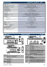
1 2 3 4 5 6 7 8 9
10
+
14 15 16 17 18 19 20
A
B
C
D
LINK POWER
SUPPLY
TTL
ECHO
GND
+
-
RS-485
-
LINK
Pb2
Pb1
Pb3
D.I.1
D.I.2
TERMINALS
1 - 2
Probe input 1 (thermostat control)
1 - 3
Probe input 2 (1st evaporator)
1 - 4
Probe input 3 (display or 2nd evaporator see par. H43)
TERMINALS ID 985/S/E/CK
5 - 6
Digital input 1
5 - 7
Digital input 2
TERMINALS ID 985/E LX
5 - 6
Digital input 2
5 - 7
Digital input 1
1 2 3 4 5 6 7 8 9
10
+
13 14 15 16 17 18 19
A
B
C
D
LINK
POWER
SUPPLY
TTL
ECHO
12
11
-
Pb2
Pb1
Pb3
D.I.2
D.I.1
ID 985/S/E/CK
WIRING DIAGRAMS
ID 985/E LX
1 2 3 4 5 6 7 8 9
+
14 15 16 17 18 19 20
A
B
C
D
LINK
POWER SUPPLY
TTL
ECHO
GND
+
-
-
12 13
RS-485
Pb2
Pb1
Pb3
D.I.1
D.I.2
TERMINALS ID 985/S/E/CK
8 - 9
Link (voltage; 8=+, 9=-) *
8 - 1/5
Link (voltage; 8=+, 1=- or 5=-) **
12 - 13
Power supply *
9 - 10
Power supply **
14 - 15 - 16
NO relay output (A) (defrost default, par.H22)
14 - 17
NO relay output (B) (compressor default, par.H21)
14 - 18
NO relay output (C) (fans default, par.H23)
19 - 20
NO relay output (D) (alarm default, par.H24)
TTL
TTL input for Copy Card
RS485
Serial for connection to Televis system
*version 95...240V
a
** version 12...24V
a
/12..36V
c
TERMINALS ID 985/E LX
8 - 9
Link (voltage; 8=+, 9=-)
10 - 11
Power supply 12V
a
12 - 13 -14
NC relay output (A) (defrost default, par.H22)
15 - 16
NO relay output (B) (compressor default, par.H21)
15 - 17
NO relay output (C) (fans default, par.H23)
18 - 19
NO relay output (D) (alarm default, par.H23)
TTL
TTL input for Copy Card and for connection to Televis
system


