GT LITHIUM V1 Workshop manual
11
©
2013
Elkington
Golf
Pty
Ltd
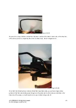
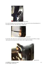
Before
you
refit
the
Top
Handle
assembly
back
onto
the
buggy,
it
is
advisable
to
place
the
two
halves
of
the
handle
together
and
ensure
that
the
Speed
Dial
in
not
binding
on
the
Top
Handle
assemble
as
pictured
in
Figure
No
14
Figure
No
14
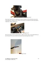
Once
you
are
certain
that
the
Speed
Dial
is
turning
correctly
without
interference,
then
re
connect
the
Speed
Switch
wiring
to
the
PCB
board
and
re
connect
the
stem
cable
wiring,
ensuring
that
each
coloured
wire
corresponds
with
the
colour
printed
on
the
terminal
block.
Fit
the
Stem
Cable
securing
bracket
and
refit
the
handle
to
the
buggy
by
referring
to
paragraph
No
4.
Test
the
operation
of
the
speed
switch
and
ensure
that
it
is
functioning
correctly
and
the
Speed
Dial
is
not
fouling
on
the
Top
Handle
assembly.
3/
REPLACING
THE
PCB
BOARD
/
DISPLAY
IN
THE
TOP
HANDLE
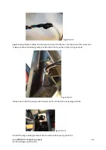
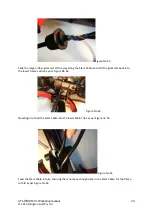
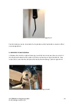
To
carry
out
this
process,
follow
the
steps
as
per
Figures
1
to
4
then
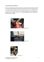
remove
the
3
screws
indicated
by
arrows,
which
secure
the
PCB
board
as
per
Figure
No
15
and
replace
the
PCB
board.
To
complete
this
procedure,
reverse
the
steps
of
Figures
1
to
4
and
test
that
the
PCB
board
is
operating
correctly
and
all
three
distance
settings
are
functioning
correctly
also.
Figure
No
15


