ELK-M1KP LCD Keypad
ELK-M1PR
J1
J2
Back (Circuit) Side of Keypad
ELK-M1PR
J1
J2
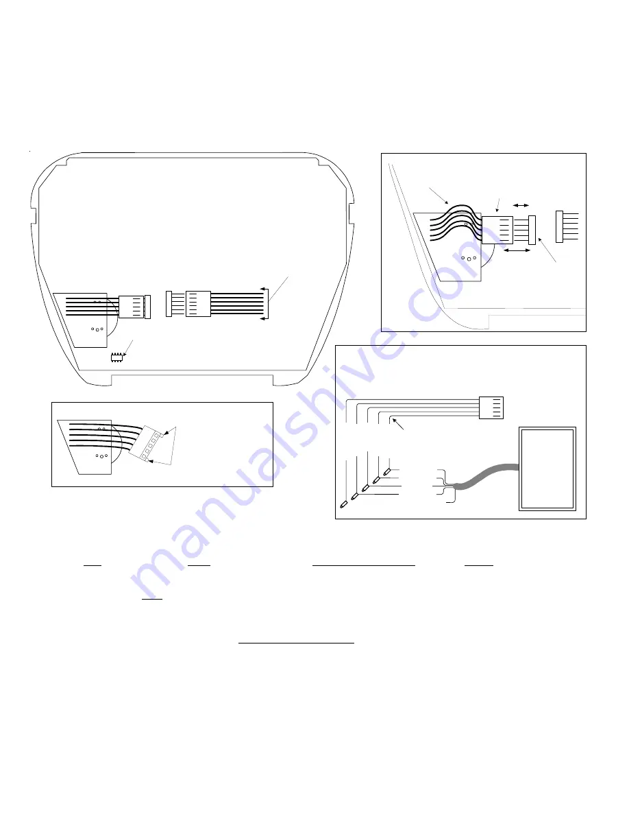
Bend (arch) the 5 wires from the M1PR wiring plug as
shown. This provides space between the plug and the
connector (J2) so that they may be attached.
J2
Connector
M1PR Wiring Plug
Detail A
Six (6) conductor plug-in data bus cable
(4 wires got to the M1 Control, 1 is a zone
input and 1 is a programmable output).
Note:
Earlier version
keypads do not have the
newer (white) polarized J2
jack. For these type
keypads; the small
polarizing tabs need to be
cut off so the connector will
fit onto the J2 jack.
ELK-M1PR
Detail B
Built-in Temperature Sensor
If the Keypad local temperature reads
too high after installation of the M1PR Mini Prox Reader, it may be
necessary to adjust the keypad temperature reading to compensate
for the added heat produced by the M1PR. Refer to the M1KP
Instructions or contact ELK Technical Support.
An ELK-106055 External Prox Reader may be connected to the ELK-M1KP
Keypad instead of the optional ELK-M1PR Internal Mini Prox Reader. This
requires an ELK-WO35A Cable Assembly (purchased separately). Splice wires
as indicated, and plug cable into connector J2. NOTE: The M1KP is also
compatible with many other brands of 26 bit Wiegand compatible readers.
White (Data 1)
Red (+12VDC)
Black (Neg)
Green (Data 0)
Brown
Whi
te (
D
at
a 1
)
R
ed (
+
12 V
D
C
)
B
lack (
N
eg)
G
re
en (
D
at
a 0)
B
row
n (
+
5 V
D
C
)
ELK-WO35A Cable Assembly
Detail C
ELK-106055
External
Prox Reader or
other brand (26
bit Wiegand)
compatible
reader.
If ext. Prox Reader requires 5 VDC then connect the brown
wires instead of the red wires. Insulate any unused wires.
INSTALLATION OF OPTIONAL ELK-M1PR INTERNAL PROXIMITY CARD READER
1. Turn Off the M1 Master Power Switch.
2. Remove the M1KP Keypad from its mounting plate, disconnect the 6 pin data bus cable, and place face down on a soft surface.
3. Locate the 1" mounting hole in the lower left corner and the 5 pin male connector marked J2 to the right of the mounting hole.
4. Position the M1PR in the 1" mounting hole with its 5 wire female cable facing towards connector J2 on the keypad circuit board.
5. Gently lift up on the 5 wire cable, then bend the white plug down to form a slight arch in the wires.
SEE DETAIL A.
This will shorten
the cable enough that it can be plugged into connector J2.
6. Reconnect the 6 pin data bus cable to connector J1 and install the keypad onto its mounting plate.
7. Turn On the M1 Master Power Switch and follow the instructions for enrolling cards or fobs
ENROLLING PROX CARDS AND FOBS
Prox cards/fobs are enrolled into a User Code location using the same procedures used to add/change User Code PINs.
1. Press the ELK key, then press the 6 key (or scroll up) to display 6 - Change User Codes. Press the RIGHT arrow key to select this
menu. A Master user code (PIN) must be entered to gain access to this menu.
2. Enter the three digit number of the desired User Code location (001 to 099) or use the UP or DOWN arrow keys to scroll through
the codes. Then select CHG by pressing the RIGHT arrow key.
3. The keypad will display any existing 4 or 6 digit code that is programmed for this user along with any programmed name.
4. Place a new (not previously enrolled) prox card/fob near the Keypad's right speaker grill, just below the Stay key. The read range is
approximately 1/8" to 3/8" from the front surface. If accepted the Keypad will beep 3 times and display the card/fob 12 digit ID.
5. If the card/fob is rejected, a low error tone and Code Not Authorized, Redo will display. Causes for reject include: A. The card/fob
has already been enrolled (duplicate codes are not allowed) OR B. The facility code in the card/fob does not match the reader
facility code. A prox reader can only read cards/fobs with a matching facility code.
6. Once a prox card/fob is enrolled in a user code location, its capabilities are set by the User Code Options found in Menu 02 of the
M1 Installer Level Programming. The commonly used options are: Arm the M1 Control, Disarm the M1 Control, or Access event.
An Access event occurs when a valid prox card/fob is read at a keypad. It will not do anything unless included in a Whenever/And/
Then Rule from the Elk-RP software. An Access event can be used to create virtually any desired reaction. i.e., turn on an output, a
light, close/open a relay, etc. The following is an example of a rule which will turn on Output 003 for 10 seconds whenever a valid prox
card/fob (with Access Option enabled) is presented at Keypad 01. This output could be used to break or make power to a door strike.
WHENEVER Keypad 01 Access is Activated
THEN Turn On Output 003 for 10 seconds.
Page 4


