T 3000 - T 3500
30
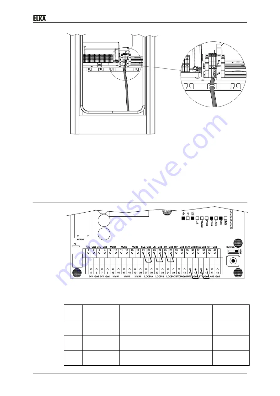
Drawing 19
Connecting the power line:
1. Lay the power line via the shortest possible way to the main switch. Make
sure the power line does not have contact with any movable mechanical
parts.
2. Connect the power line to the main switch and to the earth lead terminal.
3. Fasten/secure the power line by cable ties at the provided tabs.
8.3
Controller terminal row
Drawing 20
The following control inputs have to be bridged or occupied with contact (NC)
for operation:
1. Terminals
23 + 24
Photoelectric barrier (LS)
NC contact or
bridge
2. Terminals
25 + 26
Boom missing contact (Bm)
NC contact or
bridge
3. Terminals
41 + 42
Push button CLOSE (BTZ2)
NC contact or
bridge
4. Terminals
43 + 44
Push button STOP (BTS)
NC contact or
bridge
Summary of Contents for T 3000
Page 12: ...T 3000 T 3500 11 4 Declaration of incorporation Drawing 2...
Page 18: ...T 3000 T 3500 17 7 2 Mounting dimensions Drawing 3...
Page 34: ...T 3000 T 3500 33 8 4 Circuit diagram Drawing 21...
Page 35: ...T 3000 T 3500 34 Drawing 22...
Page 36: ...T 3000 T 3500 35 Drawing 23...
Page 37: ...T 3000 T 3500 36 Drawing 24...
Page 38: ...T 3000 T 3500 37 Drawing 25...
Page 39: ...T 3000 T 3500 38 Drawing 26...
Page 40: ...T 3000 T 3500 39 Drawing 27...
Page 42: ...T 3000 T 3500 41 10 Layout exploded drawing Drawing 28...


