© 14.11.2005 ELKA-Torantriebe GmbH u. Co. Betriebs KG Page 14 TERRA 180/182 - 250/252 – 320/322
4.4.2. Gates with one wing
a. Remove the protective foil and protective tapes from the gate opener.
b. Remove the cover plate from the underfloor housing.
c. Make sure that the adjustment clip is in its position.
d. Check that the emergency release is engaged. The gate wing should not be in either
end position.
e. Now connect the gate opener to the 5-pin connection
FAHR
on the controller MO36.
Please pay attention to the correct wiring.
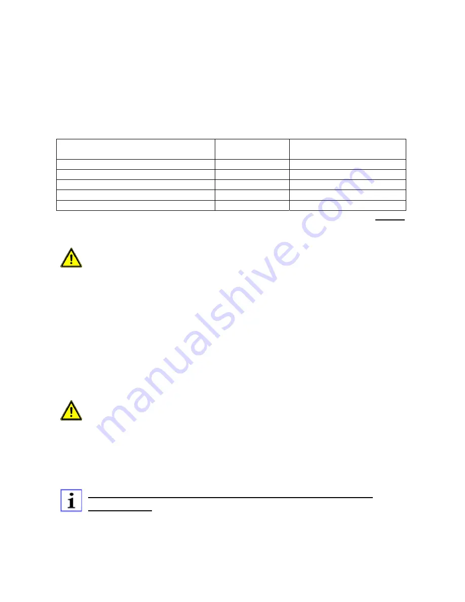
Contacts at the motor
(Cable cross section)
Mark
Contacts on the MO36
green (0.15mm²)
1
GND
white (0.15mm²)
2
IMP
brown (0.15mm²)
3
I+
blue (1.5mm²)
4
M-
brown (1.5mm²)
5
M+
Table 3
f. Connect to the mains.
Attention: During the next steps the gate wing will be moved electrically.
Make sure the range of movement is free from obstacles.
Attention: During learning the safety devices can react differently from the
normal operation.
g. Press the button
LERN
on the controller for approx. 2 seconds. The display shows
P1
.
h. Press the button
LERN
again. The display now shows
1F.
i. Now select the number of gate wings. Confirm the displayed
1F (
for one wing
)
with the
button
LERN.
j. The display shows
HA
(manual operation).
k. Now you can move the gate wing into the end positions in slow mode (dead man´s
function). The gate wing moves into direction
OPEN
only as long as button
BT
is
pressed. When button
BT
is pushed
again, the wing moves into direction
CLOSED.
l. Now move the gate wing with button BT into the end postitions OPEN and CLOSED.
The internal end stops are now adjusted but not fixed.
m. Move the gate wing with button
BT
into position „
half OPEN“
.
Attention: Do not give any further commands to the controller now.
j. Remove the plug from the 5-pin connection
FAHR.
k.
Mark the position of the pinion and the gear shaft to each other for the following
installation steps (see drawing 9).
l. Remove the marked pinion off the gear shaft.
m. Now you can reach the 8 countersunk-screws (by 6mm allen key)
.
These screws must be tightened by a torque wrench
with 45 Nm.
Use the torque wrench to fix the internal stops!


