Mechanical installation
22
8.9
Adjusting the internal stops
ATTENTION!
Risk of crushing!
During the next steps the gate will be moved electrically. During the adjustment the safety
devices can react differently from normal operation.
Make sure that the range of movement is free of obstacles.
REMARK!
For additional information regarding the controller see chapter 10.
a. Press the button
LERN
on the controller for approx. 2 seconds. The display shows
p1
.
b. Press the button
LERN
again. The display now shows
1f
.
Using the button
BT
chose
between gates with one wing (
1f
) and gates with two wings (
2f
). Confirm the choice using
button
LERN
.
The display now shows
ha
.
c. Now you can move the gate wing into the end positions in slow mode. The gate wing moves
into direction OPEN only as long as button
BT
or
BTG
is pressed. Push button
BT
or
BTG
again and the wing moves into direction CLOSED.
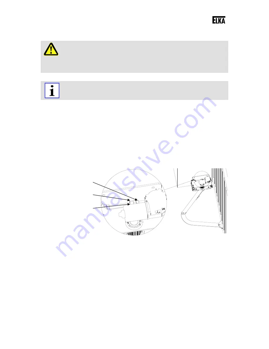
d. Using the button
BT
move the gate wing (for gates with one wing – for gates with two wings
move the main wing) into the end position OPEN. Turn the internal stop nut OPEN against the
internal stop. Fasten the internal stop nut using the counter nut.
Drawing 17
e. Using the button
BT
move the gate wing into the end position CLOSED. Turn the internal stop
nut CLOSED against the internal stop. Fasten the internal stop nut using the counter nut.
Counter nut
Internal Stopp nut
Internal stop


