Fault diagnosis
53
12 Fault
diagnosis
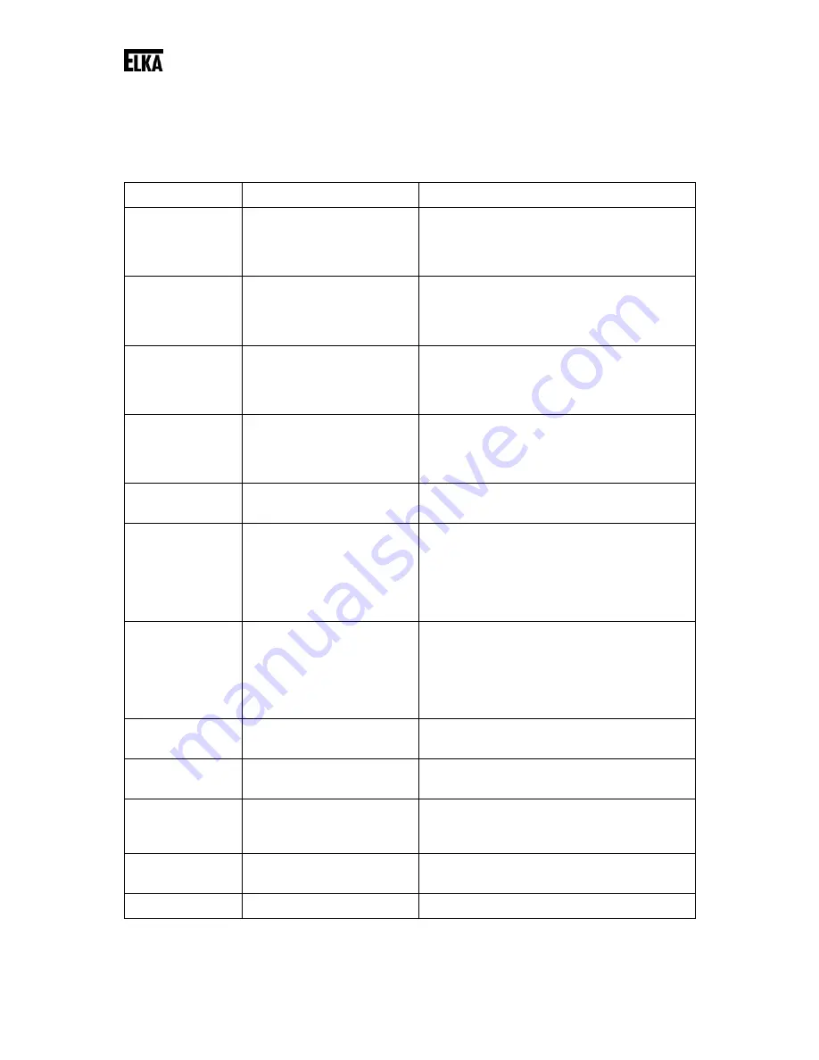
An fault is shown on the display as a code, when detected by the controller. The following faults are
recognised and displayed.
Display Fault
description
Procedure
e1
Photo-cell testing LSI failed.
Check the connected photoelectric barriers for
the interior area for function. Make sure the
1kOhm resistor is connected to the
photoelectric barrier receiver.
e2
Photo-cell testing LSA
failed.
Check the connected photoelectric barriers for
the exterior area for function. Make sure the
1kOhm resistor is connected to the
photoelectric barrier receiver.
e3
Testing safety contact
profile SLA failed.
Check the connected safety contact profiles
for direction OPEN for function. Make sure the
8.2kOhm resistor is connected as terminating
resistor.
e4
Testing safety contact
profile SLZ failed.
Check the connected safety contact profiles
for direction CLOSED for function. Make sure
the 8.2kOhm resistor is connected as
terminating resistor.
e5
Running distance exeeded
(gate was stopped).
Check end stoppers and relearn the running
distance.
e6
The power supply limit fort
he external equipment
12Vdc has been reached.
The power source load is
too high. The controller is
blocked.
Check the connected load at the terminals
12Vdc and GND (observe the max. current
drain). Check the input leads for short circuit.
e7
The power supply limit fort
he external equipment
24Vdc has been reached.
The power source load is
too high. The controller is
blocked.
Check the connected load at the terminals
24Vdc and GND (observe the max. current
drain). Check the input leads for short circuit.
e8
The memory data has been
lost / is faulty.
The controller has to be re-learned.
e9
Error in storing of data on
memory. Controller is faulty.
Return for repairs.
ea
Error in the redundant
detection of BS. Controller
is faulty.
Return for repairs.
eb
The controller detects one
of motor relays is faulty.
Return for repairs.
ec
Measuring amplifier faulty.
Return for repairs.


