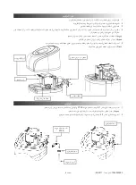
3. Install the bypass valve into the valve head using the steps below.
• Apply silicone oil to the four O-rings on the bypass valve assembly.
• Position the bypass valve with the fl owmeter on the inlet and full insert into the valve head.
• Install the clamping brackets and screws to secure the bypass valve to the valve head.
4. Snap the fl ow meter sensor into the bypass valve assembly.
5. Reinstall the top cover after connecting the cable for the valve and fl ow meter to the electronic display.
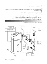
6. Move the fi ltration system into place and connect the plumbing. The connections can be made using rigid plumbing or the
provided hoses.
CAUTION:
It is important to connect the IN and OUT correctly. Reversing the fl ow can cause damage to the system.
7. Position the drain line over the drain.
NOTE:
There should be a 10cm distance between the end of the drain tube and the drain to prevent sewage from being
siphoned into the system.
8. Connect the power supply and plug it into the wall socket.
NOTE:
The electronic display will come on with all characters showing for 5s and the buzzer will sound for 1s. The unit will
then enter the normal display state.
NOTE:
Do not use a wall socket controlled by a switch.
Bypass Valve
Valve Head
Flowmeter
Clamping Bracket
Electronics
Cable
Page 5
1000003995 (Rev A - 05/2017)


