


página 9
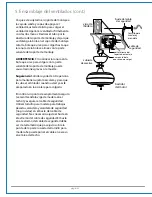
Se le recomienda poner el ventilador a prueba antes de
terminar la instalación. Localizar el interruptor corredero de
APAGADO y ENCENDIDO en el control de pared y ponerlo en
posición ENCENDIDO. Poner a prueba las velocidades del
ventilador con los botones de velocidad del ventilador. Si el
ventilador no funciona, favor de referirse a la sección
"Localización de fallas" para resolver cualquier asunto antes
de comunicarse con el Servicio al cliente.
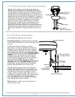
Hay que poner el ventilador en posición BAJA
antes
de poner
el ventilador en reversa. Regularlo (usando el botón )
para que circule bien el aire dependiendo de las estaciones
del año.
Un ventilador de techo le permitirá subir el
termostato en verano y bajarlo en invierno sin notar una
diferencia en su comodidad.
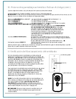
NOTA
: Si el control de pared/control remoto interfiere con
otros enseres, cambiar a otro código en el control de pared.
Si es que cambia el código,
primero desconectar la
electricidad
. Después de poner un código nuevo en el
control de pared/control remoto, volver a las instrucciones
acerca del botón SET de la sección 10 (página 9).
IMPORTANTE
: Hay que sincronizar el control remoto y el
control de pared con el ventilador para que funcionen
correctamente.
I
II
IV
VI
III
V
reversa
reversa
control de pared
control remoto
I
OFF
ON
II
III
IV
V
VI
Quitar la tapa de la batería en la parte de atrás del transmisor del control remoto.
Instalar la batería de 12 voltios (incluidas) en el transmisor y el control de pared.
IMPORTANTE
: Guardar el transmisor lejos del calor excesivo o la humedad. Para prevenir daño al transmisor, sacar la
batería si no se va a utilizar el transmisor por un tiempo extendido.
Botones de
VELOCIDAD
del ventilador
1
: usar para controlar la velocidad del ventilador de 1- 6
Botón
de
APAGADO
2
:
usar para apagar el ventilador
Botón
de
REVERSA
3
:
usar para controlar la dirección del ventilador
Botón
de
ILUMINACION
4
:
usar para controlar la luz superior o la luz inferior (si se apilca).
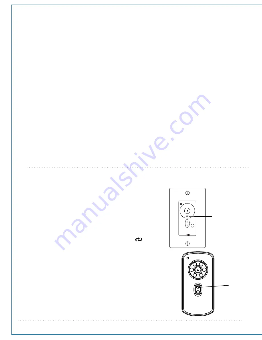
CONMUTADORES DE LAS UNIDADES DE CONTROL REMOTO
y botón
SET
5
:
Con los cortacircuitos apagados, poner los
CONMUTADORES
DE LAS UNIDADES DE CONTROL REMOTO
en el código
deseado. Encender la electricidad del ventilador, oprimir y
mantener sujeto el botón
SET
que se encuentra en la parte
trasera del control remoto y en el control de pared por
5 segundos dentro de 60 segundos de haber conectado la
electricidad que va al ventilador para sincronizarlo con el
motor del ventilador.
Función
de
REDUCTOR DE LUZ 6
:
Se determina la capacidad de bajar las luces dependiendo del tipo de
bombillas provistas con el ventilador. Si no se incluye ninguna bombilla,
no funcionará el reductor de luz.
Posición APAGADO (Off ) =
D /
Posición ENCENDIDO (On) =
ON
Interruptor corredero
ON
/
OFF 7
:
[control de pared solamente] Usar para prender o apagar
el control de pared
Volver a poner la tapa a la batería en el transmisor. Escoger el panel decorativo para el control de pared y sujetarlo
fijamente en la parte delantera del control de pared.
11. Verificación del funcionamiento del ventilador.
10. Proceso de aprendizaje automático/Activar el código (cont. )


