background image

page 3

3. Installation Preparation.

ON

OFF

ON

OFF

4. Hanging Bracket Installation.

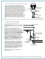
Turn off circuit breakers to current fixture from breaker panel 
and be sure operating light switch is turned to the OFF 
position. 

WARNING: 

Failure to disconnect power supply prior to installation 

may result in serious injury.

Remove existing fixture. 

WARNING:


WARNING:

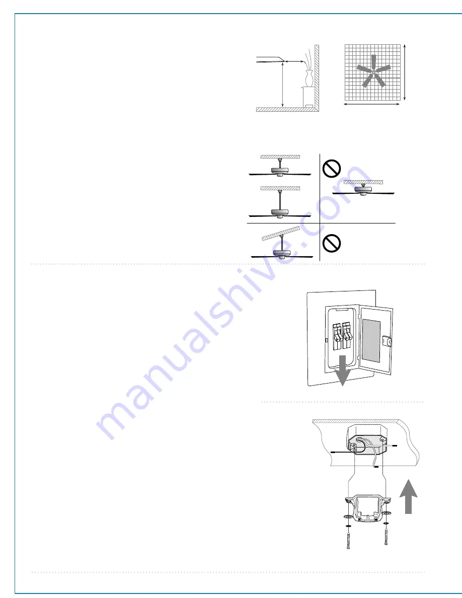
 To reduce the risk of fire, electric shock, or 

personal injury, mount to outlet box marked "Acceptable for Fan 
Support of 22.68 kg (50lbs.) or Less" and use mounting screws 
provided with the outlet box. Most outlet boxes commonly used for 
the support of lighting fixtures are not acceptable for fan support 
and may need to be replaced. Consult a qualified electrician if in 
doubt. When using an existing outlet box, be sure the outlet box is 
securely attached to the building structure and can support the full 
weight of the fan. Ensure it is clearly marked "Suitable for Fan 
Support." If not, it must be replaced with an approved outlet box. 
Failure to do so can result in serious injury.

CAUTION

: Be sure outlet box is grounded and that a ground wire 

(

GREEN

 or bare) is present.

Install hanging bracket to outlet box using original screws, 
spring washers and flat washers provided with new or original 
outlet box.

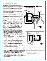
If installing on a vaulted ceiling, face opening of 

hanging bracket towards high point of ceiling. Arrange 
electrical wiring around the back of the hanging bracket and 
away from the bracket opening.

*Note

: It is very important that you use the proper hardware when 

installing the hanging bracket as this will support the fan. 

Vaulted ceiling 
angle is not to 
exceed 25 degrees.

downrod

installation

flushmount

installation

10 feet

(3.05m) (76cm)

30 

inches

12f

t.

  - 20f

t.

12ft. - 20ft.

(3.66m - 6.1m)

(3.66m - 6.1m)

blade edge

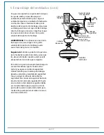
To prevent personal injury and damage, ensure 
that the hanging location allows the blades a 
clearance of 10 feet (3.05m) from the floor and 
30in. (76cm) from any wall or obstruction. 
This fan is suitable for room sizes up to 400  
square feet (37.2 square meters).

This fan can be mounted with a 

downrod

on a regular (no-slope) or vaulted ceiling. The 
hanging length can be extended by purchasing 
a longer downrod (0.5in./1.27cm diameter). 
Other installation, such as 

flushmount

, is 

not


available for this fan.

Installation requires these tools:

Phillips screwdriver, flathead screwdriver, 
adjustable pliers or wrench, stepladder, wire 
cutters, and rated electrical tape

hanging bracket

spring washers

outlet box screws

flat washers

Summary of Contents for COL72BP6

Page 1: ...mated Learning Process Activating Code pgs 8 9 Testing Your Fan pg 9 Troubleshooting pg 10 Parts Replacement pg 10 Warranty pg 10 PRINTED IN CHINA READ THESE INSTRUCTIONS AND SAVE THEM FOR FUTURE USE Installation Guide For Models COL72BP6 COL72ESP6 COL96BP6 COL96ESP6 net weight of fan 34 43 lb 15 62 kg COL72BP6 COL72ESP6 35 27 lb 16 00 kg COL96BP6 COL96ESP6 F P O F P O For Placement Only For Place...

Page 2: ...ing this fan in a DAMP location this fan must be connected to a supply circuit that is protected by a Ground Fault Circuit Interrupter GFCI to reduce the risk of personal injury electrical shock or death 5 Electrical diagrams are for reference only Light kits that are not packed with the fan must be CETL Canada or ETL USA listed and marked suitable for use with the model fan you are installing Swi...

Page 3: ...piece c downrod and hanging ball 1 piece d motor housing 1 piece e switch housing plate 1 piece f switch housing cap 1 piece g yoke cover 1 piece h blade arm 6 pieces i blade 6 pieces j safety cable already attached to motor 1 piece k canopy cover in hardware pack 1 piece l remote control transmitter 1 piece m wall control plate and decor covers 5 separate pieces n hardware packs IMPORTANT REMINDE...

Page 4: ...bracket to outlet box using original screws spring washers and flat washers provided with new or original outlet box If installing on a vaulted ceiling face opening of hanging bracket towards high point of ceiling Arrange electrical wiring around the back of the hanging bracket and away from the bracket opening Note It is very important that you use the proper hardware when installing the hanging ...

Page 5: ... this will keep the wires together when threading them through the downrod Locate canopy cover in hardware pack Loosen yoke set screws and nuts at top of motor housing Remove pin and clip from motor housing yoke Slide downrod through canopy canopy cover and yoke cover Note Canopy cover must be turned with shiny side toward the motor housing Thread safety cable and electrical wires through downrod ...

Page 6: ...ng bracket tab WARNING Failure to align slot in hanging ball with tab in hanging bracket may result in serious injury or death Tip Seek the help of another person to hold the stepladder in place and to help lift the fan up to you once you are set on the ladder Find a secure attachment point wood ceiling joist highly recommended and secure safety cable It will be necessary to use a heavy duty wood ...

Page 7: ...urrent fixture from breaker panel and be sure switch is turned to the OFF position Connect GREEN ground wire to ground from house or directly to one of the screws from the outlet box Connect one BLACK wire from wall control to BLACK hot lead wire from house Connect second BLACK wire from wall control to BLACK load wire to fan Attach wall control to outlet box and secure with screws from original w...

Page 8: ...attachment screws and washers and 18 decorative nuts in hardware packs Place blade arm on TOPSIDE of blade aligning holes in blade arm with holes in blade as shown Be sure to note label on blade indicating THIS SIDE UP and turn blade so that label faces up With fingers insert 3 blade attachment screws along with washers from the TOPSIDE of blade and 3 decorative nuts from UNDERSIDE of blade making...

Page 9: ...rews for later use Remove 1 screw from fitter plate on underside of motor and partially loosen the other 2 screws Align slotted holes in center of switch housing plate with loosened screws in fitter plate allowing molex plugs from motor housing to come through hole in middle of switch housing plate Twist switch housing plate to lock Re insert screw that was removed and secure all 3 screws Align ho...

Page 10: ...ith fan in order to properly function I OFF ON II III IV V VI I II IV VI III V reverse reverse Wall Control Remote Control 10 Automated Learning Process Activating Code cont Remove battery cover on back side of remote control transmitter Install 12 volt battery provided in transmitter and wall control IMPORTANT Store the transmitter away from excess heat or humidity To prevent damage to transmitte...

Page 11: ...tion of finishes or other parts due to time or exposure to salt air is specifically exempted under this warranty Neither Craftmade Ellington nor the manufacturer will assume any liability resulting from improper installation or use of this product In no case shall the company be liable for any consequential damages for breach of this or any other warranty expressed or implied whatsoever This limit...

Page 12: ...a de encendido Pág 8 Proceso de aprendizaje automático Activar el código Págs 8 9 Verificación del funcionamiento del ventilador Pág 9 Localización de fallas Pág 10 Piezas de repuesto Pág 10 Garantía Pág 10 peso neto del ventilador 15 62 kg 34 43 lb COL72BP6 COL72ESP6 16 00 kg 35 27 lb COL96BP6 COL96ESP6 IMPRESO EN CHINA LEER ESTAS INSTRUCCIONES Y GUARDARLAS PARA UTILIZACION FUTURA Guía de instala...

Page 13: ...nectores para cable que se debe usar ADVERTENCIA Si va a utilizar este ventilador en un lugar HÚMEDO hay que conectar el ventilador a un circuito de alimentación que esté protegido por un Interruptor de Circuito de Falla de Tierra GFCI por sus siglas en inglés para reducir el riesgo de daño corporal descarga eléctrica o la muerte 5 Los diagramas eléctricos son únicamente para referencia Los juegos...

Page 14: ...ntrol de pared placa y paneles decorativos 5 unidades distintas n paquetes de artículos de ferretería página 2 Abrir el empaque cuidadosamente Sacar los artículos del embalaje Sacar el motor y ponerlo en una alfombra o en el embalaje para evitar rayar el acabado Guardar la caja de cartón o el empaquetamiento original en caso de que tenga que mandar el ventilador para alguna reparación Comprobar la...

Page 15: ...si es necesario puede resultar en lesiones graves PRECAUCION Asegurarse de que la caja de salida esté conectada a tierra correctamente y que haya un conductor a tierra cable VERDE o pelado Instalar el soporte de montaje utilizando los tornillos originales las arandelas de resorte y las arandelas planas de su nueva o existente caja de salida Si hace la instalación en un techo abovedado colocar el s...

Page 16: ...e la cubierta decorativa en uno de los paquetes de artículos de ferretería Aflojar los tornillos de fijación del cuello y las tuercas en el cuello del bastidor del motor Quitar el perno y la clavija del cuello del bastidor del motor Pasar el tubo por la cubierta decorativa la tapa de la cubierta decorativa y la cubierta del cuello Nota Se tiene que voltear la tapa de la cubierta decorativa para qu...

Page 17: ...oporte de montaje ADVERTENCIA El no alinear la ranura en la bola que sirve para colgar con la parte saliente del soporte de montaje puede causar lesiones graves o la muerte Sugerencia Solicitar ayuda de otra persona para mantener sujeto la escalera y para que le suba el ventilador cuando usted ya esté preparado en la escalera para colgarlo Encontrar un punto de acoplamiento seguro se recomienda la...

Page 18: ...l lado Como una medida de seguridad adicional envolver cada conector para cable con cinta aisladora Delicadamente meter los conectores para cable dentro de la caja de salida ADVERTENCIA CONECTAR LOS CABLES SOLAMENTE EN EL ORDEN QUE SIGUE ADVERTENCIA Apagar los cortacircuitos en el panel de electricidad que suplen corriente a la caja de salida y asegurarse de que el interruptor de luz esté APAGADO ...

Page 19: ...os y arandelas y 18 tuercas decorativas en uno de los paquetes de artículos de ferretería Colocar un brazo para el aspa en el LADO SUPERIOR del aspa alineando los agujeros del brazo para el aspa con los del aspa como se muestra Fijarse en la etiqueta en el aspa que indica ESTE LADO HACIA ARRIBA y voltear el aspa para que la etiqueta esté orientada hacia arriba Con los dedos introducir 3 tornillos ...

Page 20: ...ndido con los agujeros en la placa de la caja de encendido Volver a introducir los tornillos que se quitaron anteriormente y asegurar los 4 tornillos con un destornillador de estrella Phillips placa de la caja de encendido bastidor del motor placa de conexión conexiones tipo molex cubierta de la caja de encendido 10 Proceso de aprendizaje automático Activar el código control remoto control de pare...

Page 21: ...en el transmisor y el control de pared IMPORTANTE Guardar el transmisor lejos del calor excesivo o la humedad Para prevenir daño al transmisor sacar la batería si no se va a utilizar el transmisor por un tiempo extendido Botones de VELOCIDAD del ventilador 1 usar para controlar la velocidad del ventilador de 1 6 Botón de APAGADO 2 usar para apagar el ventilador Botón de REVERSA 3 usar para control...

Page 22: ...e marino bajo esta garantía Ni Craftmade Ellington ni el fabricante se harán responsables por lo que pasa por una instalación inadecuada o el uso impropio de este producto La compañía no se hará responsable en ningún caso de ningún daño emergente por incumplimiento de esta o cualquier otra garantía expresada o implicada en absoluto Esta limitación de daños emergentes no se aplicará en estados dond...

Reviews: