background image

1. Unpacking Your Fan.

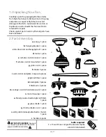
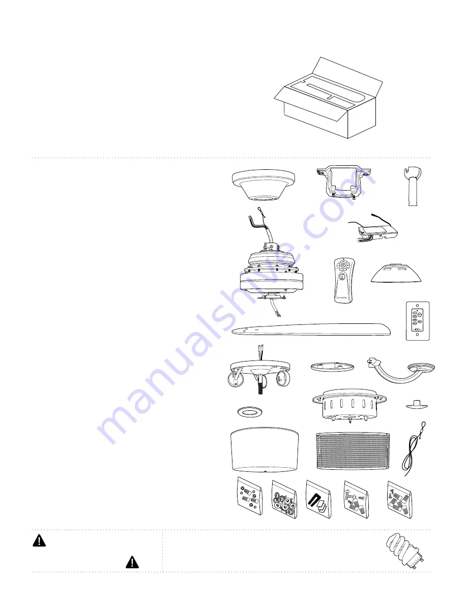
2. Parts Inventory.

a

. canopy. 1 piece

b

. hanging bracket. 1 piece

c

. 8in. downrod and hanging ball. 1 piece

d

. motor. 1 piece

e

. remote control receiver. 1 piece

f

. remote control transmitter. 1 piece

g

. yoke cover. 1 piece

h

. blade. 5 pieces

i

. wall control and plate. 2 separate pieces

j

. light kit fitter. 1 piece

k

. blade plate. 5 pieces

l

. blade arm. 5 pieces

m.

 canopy cover (in hardware pack). 1 piece

n

. motor housing. 1 piece

o

. finial (pre-attached to light kit fitter).

1 piece

p

. glass shade. 1 piece

q

. chrome shade cover. 1 piece

r.

 safety cable (already attached to motor).

1 piece

s

. hardware packs

page 2

a

b

d

c

Carefully open the packaging. Remove items 
from Styrofoam inserts. Remove motor housing 
and place on carpet or Styrofoam to avoid 
damage to finish. Do not discard fan carton or 
Styrofoam inserts should this fan need to be 
returned for repairs.
Check against parts inventory that all parts have 
been included.


p

bulbs required:

3 x 13 watt max. compact fluorescent bulbs,

size GU24 (included)

e

f

o

i

h

l

j

k

m

n

g

q

r

w/ remote

w/ wall
control

s


IMPORTANT REMINDER

: You must 

use the parts provided with this fan for
proper installation and safety.

Summary of Contents for E-BAS54CH5LKRW

Page 1: ...INSTRUCTIONS AND SAVE THEM FOR FUTURE USE Installation Guide E192641 Table of Contents Safety Tips pg 1 Unpacking Your Fan pg 2 Parts Inventory pg 2 Installation Preparation pg 3 Hanging Bracket Inst...

Page 2: ...or there is more than one house wire to connect to the two fan lead wires consult an electrician for the proper size wire connectors to use 5 Electrical diagrams are for reference only Light kits tha...

Page 3: ...ece p glass shade 1 piece q chrome shade cover 1 piece r safety cable already attached to motor 1 piece s hardware packs page 2 a b d c Carefully open the packaging Remove items from Styrofoam inserts...

Page 4: ...lable for this fan Turn off circuit breakers to current fixture from breaker panel and be sure operating light switch is turned to the OFF position WARNING Failure to disconnect power supply prior to...

Page 5: ...ctrical tape to the ends of the electrical wires this will keep the wires together when threading them through the downrod Locate canopy cover in hardware pack Loosen yoke set screws and nuts in yoke...

Page 6: ...r Bare is present Make sure all electrical connections comply with Local Codes or Ordinances and the National Electrical Code If you are unfamiliar with electrical wiring or if the house building wire...

Page 7: ...t right Wrap each wire connector separately with electrical tape as an extra safety measure Gently push wires and taped wire connectors into outlet box Use a ballpoint pen or a small screwdriver to se...

Page 8: ...ew holes on topside of the motor and attach blade arm with lock washers and blade arm screws Before securing screws permanently repeat this procedure with remaining blade arms Secure all screws Note T...

Page 9: ...ock Re insert screw that was previously removed and tighten all 3 screws securely diagram 3 Remove finial from light kit fitter diagram 3 Install 3 compact fluorescent 13 watt max bulbs size GU24 incl...

Page 10: ...battery sold separately in transmitter Note Leave battery connected but outside of battery compartment until learning process is complete Restore electrical power and then set slider switch on wall c...

Page 11: ...witch on wall control and set to the ON position Test light and dimmer function and then test fan speeds Next locate remote control Start with the light OFF and test the light ON OFF function by press...

Page 12: ...s where prohibited Problem Fan fails to operate Solutions 1 Check power to wall switch wall control 2 Check to be sure code switches in remote control transmitter and wall control are set properly 3 V...

Reviews: