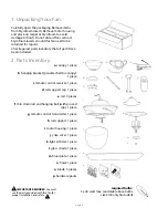
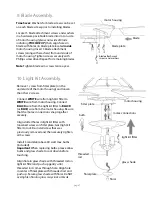
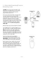
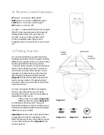
background image

5. Fan Assembly. (cont.) 

page 5

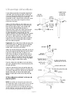
hanging bracket tab

hanging ball slot

6. Wiring.

CAUTION

Be sure outlet box is properly grounded 

and that a ground wire (

GREEN

 or Bare) is present.

Make sure all electrical connections comply with 
Local Codes or Ordinances and the National 
Electrical Code. If you are unfamiliar with electrical 
wiring or if the house/building wires are different 
colors than those referred to in the diagram to the 
right, please use a qualified electrician.

DANGER: 

If using this fan in a DAMP location, this 

fan must be connected to a supply circuit that is 
protected by a Ground Fault Circuit Interrupter 
(GFCI) to reduce the risk of personal injury, 
electrical shock or death.

Wire the receiver with wire connectors provided 
as shown in diagram at right.

Tip:

 While you are wiring, keep in mind that wires 

must not obstruct receiver from sliding into 
hanging bracket.

* Wrap each wire connector separately with 
electrical tape as an extra safety measure.

Insert receiver into hanging bracket (flat side up) 
and gently push taped wire connectors into 
outlet box. Allow antenna from remote control 
receiver to hang out of the hanging bracket.

black

black

black

from receiver

from fan

from ceiling

from receiver

white

white

blue

blue

black supply wire

ground (green

or bare)

white supply wire

white

AC IN N

AC IN L

receiver

black

whit

e

With the hanging bracket secured to the outlet 
box and able to support the fan, you are now 
ready to hang your fan. Grab the fan firmly with 
two hands. Slide downrod through opening in 
hanging bracket and let hanging ball rest on the 
hanging bracket. Turn the hanging ball slot until it 
lines up with the hanging bracket tab.

WARNING

: Failure to align slot in hanging ball 

with tab in hanging bracket may result in serious 
injury or death.

Tip

: Seek the help of another person to hold the 

stepladder in place and to help lift the fan up to 
you once you are set on the ladder.

*

antenna

Modifications not approved by the party responsible for compliance could 
void the user's authority to operate the equipment.

*NOTE: This equipment has been tested and found to comply with the limits for a Class B digital 
device, pursuant to Part 15 of the FCC Rules. These limits are designed to provide reasonable 
protection against harmful interference in a residential installation. This equipment generates, uses 
and can radiate radio frequency energy and, if not installed and used in accordance with the 
instructions, may cause harmful interference to radio communications. However, there is no 
guarantee that interference will not occur in a particular installation. If this equipment does cause 
harmful interference to radio or television reception, which can be determined by turning the 
equipment off and on, the user is encouraged to try to correct the interference by one or more of the 
following measures: 
        *      Reorient or relocate the receiving antenna. 
        *      Increase the separation between the equipment and receiver. 
        *      Connect the equipment into an outlet on a circuit different from that to which the

receiver is connected. 

Consult the dealer or an experienced radio/TV technician for help. 

ground
(green or bare)

Summary of Contents for E-KM52ABZ5LKRCI

Page 1: ...Control Operation pg 9 Testing Your Fan pg 9 Troubleshooting pg 10 Warranty pg 10 Parts Replacement pg 10 net weight of fan 29 7 lb 13 47 kg PRINTED IN CHINA READ THESE INSTRUCTIONS AND SAVE THEM FOR...

Page 2: ...ponding fan lead wires consult an electrician for the proper size wire connectors to use WARNING If using this fan in a DAMP location this fan must be connected to a supply circuit that is protected b...

Page 3: ...o canopy 1 piece c remote control receiver 1 piece d rod support cap 1 piece e rod 3 pieces f 10in downrod and hanging ball with pin and clip 1 piece g remote control transmitter 1 piece h rod support...

Page 4: ...er panel and be sure operating light switch is turned to the OFF position WARNING Failure to disconnect power supply prior to installation may result in serious injury Remove existing fixture WARNING...

Page 5: ...of the downrod should be noted as having a set screw hole use this hole when setting the set screw Insert stop pin into top of extended downrod and raise hanging ball Be sure stop pin aligns with slo...

Page 6: ...firmly with two hands Slide downrod through opening in hanging bracket and let hanging ball rest on the hanging bracket Turn the hanging ball slot until it lines up with the hanging bracket tab WARNI...

Page 7: ...th Phillips screwdriver Remember that antenna for remote control receiver must rest outside of hanging bracket Hook one end of rod to loop on motor housing Adjust rod support to top end of rod so it h...

Page 8: ...up gently until threaded rod comes through hole Align hole in center of finial plate with threaded rod and push up Secure glass shade with finial Do NOT overtighten finial as glass may crack or break...

Page 9: ...ide of transmitter Use a ballpoint pen or a small screwdriver to set the code switches 1 through 4 for the transmitter Note Since this fan comes with incandescent bulbs the dimmer switch labeled D and...

Page 10: ...If the remote control operates all of the functions of the fan and light battery has been installed correctly diagram 1 If fan and or light does do not function please refer to Troubleshooting section...

Page 11: ...rt 1 800 486 4892 to request one 2 Check to be sure set screw s on motor housing yoke is are tightened securely 3 Check to be sure set screw on hanging ball is tightened securely Parts Replacement WAR...

Page 12: ...8 Funcionamiento del control remoto P g 9 Verificaci n del funcionamiento del ventilador P g 9 Localizaci n de fallas P g 10 Garant a P g 10 Piezas de repuesto P g 10 IMPRESO EN CHINA LEER ESTAS INSTR...

Page 13: ...incipales del ventilador al cual corresponda cada uno consultar con un electricista para informarse sobre el tama o correcto de conectores para cable que se debe usar ADVERTENCIA Si va a utilizar este...

Page 14: ...remoto 1 unidad d tapa del soporte para las varitas 1 unidad e varita 3 unidades f tubo de 25 4cm y bola que sirve para colgar con perno y clavija 1 unidad g transmisor del control remoto 1 unidad h...

Page 15: ...illos junto con las arandelas de estrella guardarlos para uso m s adelante Girar la cubierta decorativa para sacar el soporte de montaje Instalar el soporte de montaje utilizando los tornillos origina...

Page 16: ...agujero al colocar el tornillo de fijaci n Introducir el perno de tope en la parte de arriba del tubo m s largo y subir la bola que sirve para colgar Asegurarse de que el perno de tope se ponga en l...

Page 17: ...la caja de salida y capaz de apoyar el ventilador usted est listo para colgar el ventilador Agarrar el ventilador firmemente con las dos manos Deslizar el tubo por la abertura del soporte de montaje y...

Page 18: ...el bastidor del motor y el soporte para las varitas Si las varitas se caen f cilmente ajustar el soporte para las varitas de nuevo ajustando el tornillo de fijaci n del soporte para las varitas de nu...

Page 19: ...s veces al a o Quitar 1 tornillo de la placa de conexi n en la parte inferior del bastidor del motor y aflojar los otros 2 tornillos Conectar el cable BLANCO del conectador para el juego de luz al cab...

Page 20: ...as unidades de control remoto 1 a 4 en el transmisor Nota Ya que este ventilador viene con bombillas incandescentes el interruptor del reductor de luz etiquetado D y X est programado de antemano en po...

Page 21: ...eductor de luz oprimiendo el bot n por m s de 2 segundos Si el control remoto maneja todas las funciones de ventilador y luz se ha instalado bien la bater a diagrama 1 Si el ventilador y o la luz no f...

Page 22: ...e que no tuvo xito el proceso de aprendizaje entre el ventilador y el transmisor del control remoto y que no se activ el c digo Desconectar la electricidad quitar la tapa de la bater a en la parte de...

Reviews: