background image

page 8

I

t is recommended that you test fan before finalizing 

installation. Restore power from circuit box and light switch 
(if applicable). Test fan speeds with the pull chain on switch 
housing. Start at the OFF position (no blade movement). First 
pull will set the fan to HI. Second pull will set the fan to 
MEDIUM. Third pull will set the fan to LOW. Fourth pull will 
re-set the fan to OFF setting. Test lights with pull chain in the 
middle. If fan and/or lights do (does) not function, please 
refer to "Troubleshooting" section to solve any issues before 
contacting Customer Service.

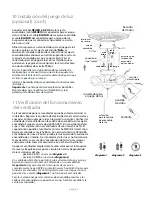
Turn fan completely off 

before

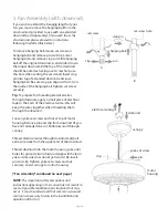
 moving the reverse switch. Set 

reverse switch to recirculate air depending on the season:
 

- DOWN position in summer 

(

diagram 1

)


- UP position in winter 

(

diagram 2

)

A ceiling fan will allow you to raise your thermostat setting in 
summer and lower your thermostat setting in winter without 
feeling a difference in your comfort.

Important:

 Reverse switch must be set either completely UP 

or completely DOWN for fan to function. If the reverse switch 
is set in the middle position 

(

diagram 3

)

, fan will not operate.

Attach pull chain extensions supplied or custom pull chain 
extensions (sold separately) to the ends of the pull chains.

11. Testing Your Fan.

10. Light Kit Assembly (Optional).
(cont.)

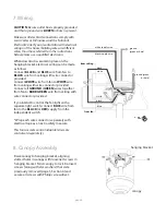
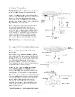
Connect 

BLACK

 (or 

BLUE

) wire from switch 

housing to 

BLACK

 wire from light kit fitter. 

Connect 

WHITE

 wire from switch housing to 

WHITE

 wire from light kit fitter. Be sure that 

molex connections snap together securely.

Align holes in light kit fitter with holes in switch 
housing. (

Note

: The gap on the top edge of the 

switch housing cap must align with the reverse 
switch on the switch housing for the proper fit.) 
Attach light kit fitter with screws that were 
removed on previous page. Securely tighten all 3 
screws with Phillips screwdriver.

Attach 4 glass shades using thumbscrews 
provided in one of the hardware packs. 

Do NOT 

overtighten thumbscrews as glass may crack or 
break.

Install 4 candelabra base 40 watt max. bulbs 
(included).

Important

:


When replacing bulbs, please allow 

bulb(s) and glass shade(s) to cool down before 
touching them.

diagram 1

diagram 2

diagram 3

switch

housing

motor 

housing 

pull chain extension

for fan

reverse

 switch


black wire

black

(or blue)

wire

white

wire

molex connections

white wire

thumb-

screws

glass shade

light kit fitter

bulb

light pull chain
extension

Summary of Contents for E-MAN52ABZ5C4

Page 1: ...pg 6 Canopy Assembly pg 6 Blade Assembly pg 7 Light Kit Assembly Optional pgs 7 8 Testing Your Fan pg 8 Troubleshooting pg 9 Warranty pg 9 Parts Replacement pg 9 READ THESE INSTRUCTIONS AND SAVE THEM...

Page 2: ...rger than 12 gauge or there is more than one house wire to connect to the corresponding fan lead wires consult an electrician for the proper size wire connectors to use 5 Electrical diagrams are for r...

Page 3: ...g h i j 1 Unpacking Your Fan Carefully open the packaging Remove items from Styrofoam inserts Remove motor housing and place on carpet or Styrofoam to avoid damage to finish Do not discard fan carton...

Page 4: ...current fixture from breaker panel and be sure operating light switch is turned to the OFF position WARNING Failure to disconnect power supply prior to installation may result in serious injury Remove...

Page 5: ...electrical tape to the ends of the electrical wires this will keep the wires together when threading them through the downrod Loosen yoke set screws and nut at top of motor housing Remove pin and cli...

Page 6: ...eveal 6 holes Notice that 3 holes are larger than the others If there are only 3 screws in top of motor housing please proceed to next paragraph If there are 6 screws in top of motor housing removed e...

Page 7: ...om ceiling with wire connector provided Connect WHITE wire from fan to WHITE wire from ceiling with wire connector provided Connect all GROUND GREEN wires together from fan to BARE GREEN wire from cei...

Page 8: ...s twice a year plastic motor lock motor housing Remove 3 screws and star washers from switch housing cap If you wish to use your fan WITHOUT the light kit align holes in switch housing cap with holes...

Page 9: ...m 3 fan will not operate Attach pull chain extensions supplied or custom pull chain extensions sold separately to the ends of the pull chains 11 Testing Your Fan 10 Light Kit Assembly Optional cont Co...

Page 10: ...ng ball is tightened securely CRAFTMADE ELLINGTON LIFETIME WARRANTY CRAFTMADE ELLINGTON warrants this fan to the original household purchaser for indoor use under the following provisions 1 YEAR WARRA...

Page 11: ...alaci n el ctrica P g 6 Colocaci n de la cubierta decorativa P g 6 Colocaci n de las aspas P g 7 Instalaci n del juego de luz opcional P gs 7 8 Verificaci n del funcionamiento del ventilador P g 8 Loc...

Page 12: ...el calibre del cable de la casa es superior al 12 o hay m s de un cable de la casa para conectar a los cables principales del ventilador al cual corresponda cada uno consultar con un electricista para...

Page 13: ...rias 4 bombillas de base candelabro de 40 vatios m x incluidas 1 Desempaquetado del ventilador Abrir el empaque cuidadosamente Sacar los art culos del embalaje Sacar el motor y ponerlo en una alfombra...

Page 14: ...aja de salida y asegurarse de que el interruptor de luz est APAGADO ADVERTENCIA El no desconectar el suministro de fuerza antes de la instalaci n puede tener por resultado lesiones graves Quitar el ap...

Page 15: ...ese extremo usar ese agujero al colocar el tornillo de fijaci n Introducir el perno de tope en la parte de arriba del tubo m s largo y subir la bola que sirve para colgar Asegurarse de que el perno d...

Page 16: ...ubierta decorativa bastidor del motor Quitar el anillo de hule de la cubierta decorativa y echarlo a un lado dejando que se vean 6 agujeros Darse cuenta de que 3 de ellos son m s grandes que los demas...

Page 17: ...os PELADOS VERDES del techo con un conector para cable provisto Si usted piensa controlar la luz del ventilador con un interruptor distinto conectar el cable AZUL del ventilador al conductor NEGRO o R...

Page 18: ...aspa soporte de pl stico del motor Quitar los 3 tornillos y las arandelas de estrella de la cubierta de la caja de encendido Si desea utilizar el ventilador SIN el juego de luz alinear los agujeros en...

Page 19: ...des del ventilador con la cadena de encendido en la caja de encendido Empezar en estado de APAGADO sin movimiento de las aspas Con el primer tir n el ventilador estar en marcha ALTA El segundo tir n p...

Page 20: ...bien el tornillo de fijaci n en la bola que sirve para colgar Para piezas o informaci n referirse al Inventario de piezas en la p gina 2 Servicio al cliente de Craftmade Ellington 1 800 486 4892 www e...

Reviews: