background image

page 4

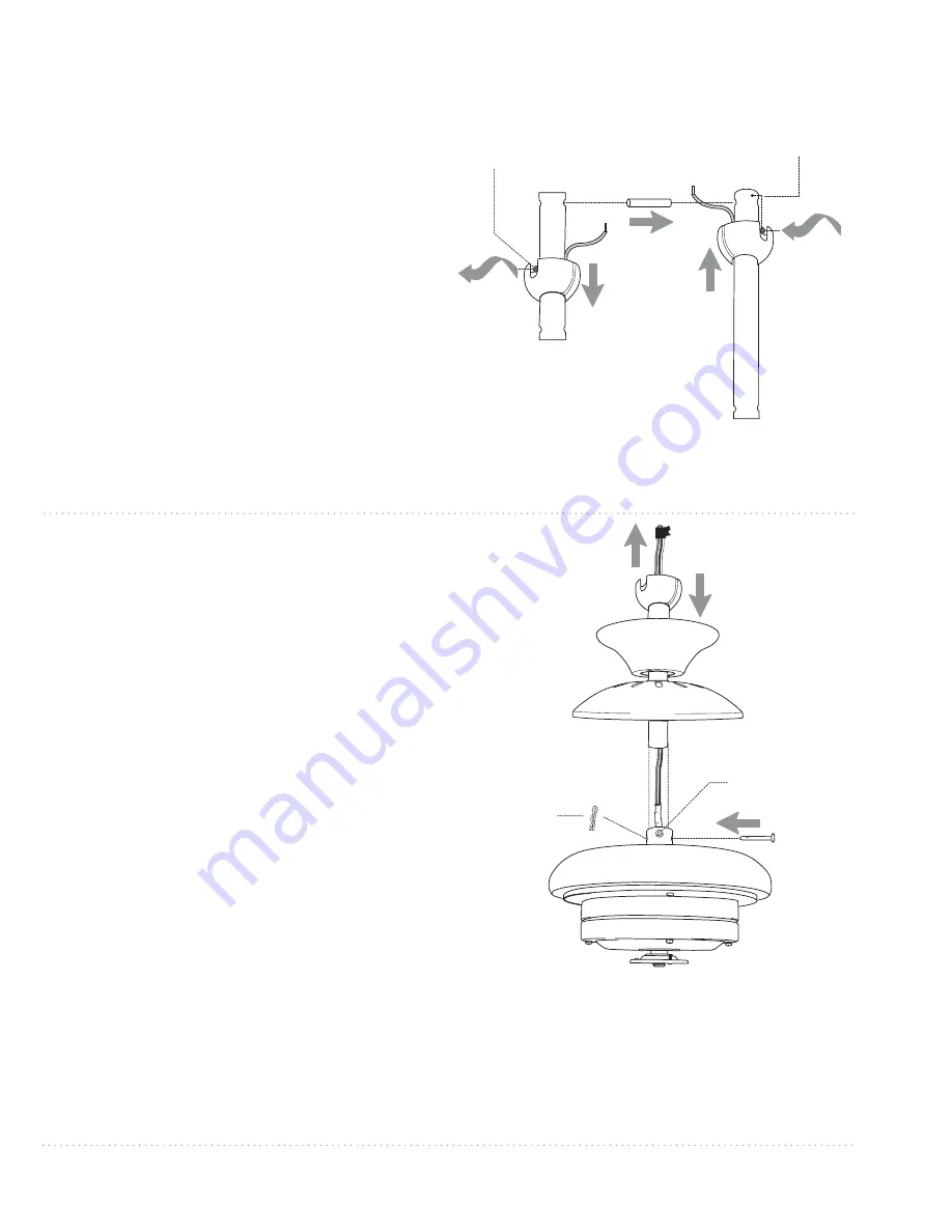
5. Fan Assembly.

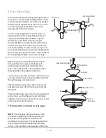
yoke set screw

set screw hole

set screw

hanging ball

stop pin

downrod

electrical wiring

canopy

yoke cover

pin

clip

If you wish to extend the hanging length of your 
fan, you must remove the hanging ball from the 
6in. downrod provided to use with an extended 
downrod (sold separately). [

If you wish to use the 

6in. downrod, please proceed to instructions 
following the dotted line below.

]

To remove hanging ball, loosen set screw on 
hanging ball, lower hanging ball and remove 
stop pin. Slide hanging ball off the original 
downrod, A, and slide it down the longer 
downrod, B (the top of the downrod should be 
noted as having a set screw hole; use this hole 
when setting the set screw). Insert stop pin into 
top of extended downrod and raise hanging ball. 
Be sure stop pin aligns with slots on the inside of 
the hanging ball. Tighten set screw securely. 

Tip

: To prepare for threading electrical wires 

through downrod, apply a small piece of 
electrical tape to the ends of the electrical 
wires--this will keep the wires together when 
threading them through the downrod.

Loosen yoke set screws and nuts and remove pin 
and clip at top of motor housing. Slide downrod 
through canopy and yoke cover.

Thread electrical wires through downrod and 
pull extra wire slack from the upper end of the 
downrod.

Place downrod into the motor housing yoke and 
re-insert pin and clip that were just removed. 
Tighten yoke set screws and nuts securely. Lower 
yoke cover to motor housing.

["Fan Assembly" continued on next page.]

NOTE

:  The important safety precautions and 

instructions appearing in the manual are not 
meant to cover all possible conditions and 
situations that may occur.  It must be understood 
that common sense and caution are necessary 
factors in the installation and operation of this fan.

motor
 housing

Summary of Contents for E-SBF58AN5LKRCR2

Page 1: ...r Model E SBF58AN5LKRCR2 F P O F P O For Placement Only For Placement Only Please show photo of RC as well Please show photo of RC as well Table of Contents Safety Tips pg 1 Unpacking Your Fan pg 2 Pa...

Page 2: ...re is more than one house wire to connect to the corresponding fan lead wires consult an electrician for the proper size wire connectors to use 5 Electrical diagrams are for reference only Light kits...

Page 3: ...trol receiver 1 piece m hardware packs a b c d e f g h i j m k l Carefully open the packaging Remove items from Styrofoam inserts Remove motor housing and place on carpet or Styrofoam to avoid damage...

Page 4: ...ox screws flat washers Turn off circuit breakers to current fixture from breaker panel and be sure operating light switch is turned to the OFF position WARNING Failure to disconnect power supply prior...

Page 5: ...on the inside of the hanging ball Tighten set screw securely Tip To prepare for threading electrical wires through downrod apply a small piece of electrical tape to the ends of the electrical wires th...

Page 6: ...ceiver CAUTION Be sure outlet box is properly grounded and that a ground wire GREEN or Bare is present Make sure all electrical connections comply with Local Codes or Ordinances and the National Elect...

Page 7: ...ks are installed with blade arm screws discard plastic motor locks save blade arm screws and lock washers to secure blade arms Align blade arm holes with motor screw holes and attach blade arm with lo...

Page 8: ...it fitter and then align the slotted holes in the light kit fitter with the loosened screws in the shade fitter Twist the light kit fitter to lock Re insert the screw that was previously removed Tight...

Page 9: ...ll screwdriver to set the code switches 1 through 4 for the transmitter Use the same number sequence used when wiring the wall control in Section 6 Locate dimmer switch labeled D and X to the right of...

Page 10: ...trol do does not operate all of the fan light functions refer to Troubleshooting section to solve any issues before contacting Customer Service Fan must be on LOW before setting the fan to reverse dir...

Page 11: ...ote control transmitter and wall control may not have been successful and code was not activated Turn off power and repeat instructions in the last paragraph of Section 10 page 8 Problem Fan wobbles S...

Reviews: