background image

page 5

5. Fan Assembly (with downrod). (cont.)

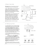
6. Fan Assembly (flushmount).

canopy

canopy cover

motor housing

Remove and set aside canopy cover to reveal 6 
holes. Notice that 3 of these holes are larger than 
the rest of them.

If there are only 

3

 screws in top of motor 

housing, please proceed to next paragraph. If 
there are 

6

 screws in top of motor housing, 

remove every other screw and lock washer.

Thread wiring through canopy. Place canopy 
over yoke, aligning larger holes in canopy with 
the 3 existing screws in top of motor housing. 
Insert the 3 screws and 3 lock washers that were 
removed (if there were only 3 screws located in 
top of motor housing, these screws/lock washers 
will be located in one of the hardware packs) into 
the remaining holes. Securely tighten these 
screws.

To prepare the fan for wiring, hang fan onto 
hanging bracket by sliding the canopy over the 
hanging bracket tab. (Use one of the non-slotted 
holes on the rim of the canopy to do so.)

hanging ball slot

hanging bracket tab

canopy

motor housing

hanging bracket tab

canopy

yoke

With the hanging bracket secured to the outlet 
box and able to support the fan, you are now 
ready to hang your fan. Grab the fan firmly with 
two hands. Slide downrod through opening in 
hanging bracket and let hanging ball rest on the 
hanging bracket. Turn the hanging ball slot until 
it lines up with the hanging bracket tab.

Tip

: Seek the help of another person to hold the 

stepladder in place and to lift the fan up to you 
once you are set on the ladder.

Continue to "Wiring" section for wiring diagram.

Summary of Contents for GD52ABZ5

Page 1: ...FOR FUTURE USE Table of Contents Safety Tips pg 1 Unpacking Your Fan pg 2 Parts Inventory pg 2 Installation Preparation pg 3 Hanging Bracket Installation pg 3 Fan Assembly pgs 4 5 Wiring pg 6 Canopy...

Page 2: ...e is larger than 12 gauge or there is more than one house wire to connect to the two fan lead wires consult an electrician for the proper size wire connectors to use 5 Electrical diagrams are for refe...

Page 3: ...inserts should this fan need to be returned for repairs Check against parts inventory that all parts have been included IMPORTANT REMINDER You must use the parts provided with this fan for proper ins...

Page 4: ...p to 400 square feet 37 2 square meters 7 feet 2 13m 76cm 30 inches 12ft 20ft 12ft 20ft 3 66m 6 1m 3 66m 6 1m blade edge Turn off circuit breakers to current fixture from breaker panel and be sure ope...

Page 5: ...w hole use this hole when setting the set screw Insert stop pin into top of extended downrod and raise hanging ball Be sure stop pin aligns with slots on the inside of the hanging ball Tighten set scr...

Page 6: ...ill be located in one of the hardware packs into the remaining holes Securely tighten these screws To prepare the fan for wiring hang fan onto hanging bracket by sliding the canopy over the hanging br...

Page 7: ...qualified electrician Note Excess lead wire length from the fan can be cut to the desired length and then stripped When fan is secured in place on the hanging bracket electrical wiring can be made as...

Page 8: ...eeds with pull chain on switch housing diagram 1 Start at the OFF position no blade movement First pull will set the fan to HI Second pull will set the fan to MEDIUM Third pull will set the fan to LOW...

Page 9: ...e fan motor fails to operate satisfactorily when failure results from normal use Parts used in the repair will be billed to the purchaser at prevailing prices at time of repair The purchaser shall be...

Reviews: