background image

4. Hanging Bracket Installation.

Turn off circuit breakers to current fixture from breaker 
panel and be sure operating light switch is turned to 
the OFF position. (

diagram a

)

WARNING: 

Failure to disconnect power supply prior to 

installation may result in serious injury.

Remove existing fixture. 

WARNING:

 When using an existing outlet box, be sure 

the outlet box is securely attached to the building 
structure and can support the full weight of the fan. 
Ensure outlet box is clearly marked "Suitable for Fan 
Support." If not, it must be replaced with an approved 
outlet box. Failure to do so can result in serious injury.

CAUTION

Be sure outlet box is grounded properly and 

that a ground wire (

GREEN

 or bare) is present.

Locate mounting screws on underside of mounting 
plate. 

Remove

 the mounting screw located next to RED 

DOT, along with the lock washer--

save for later use

Partially loosen the other 3 mounting screws. 
(

diagram b

)

Secure mounting plate to outlet box using original 
screws, spring washers and flat washers  provided with 
new or original outlet box.

Pull wires from outlet box 

through center hole in mounting plate. (

diagram c

)

*

Note

: It is very important that you use the proper 

hardware when installing the mounting plate as this will 
support the fan.

page 3

ON

OFF

ON

OFF

3. Installation Preparation.

This fan can be mounted as a 

flushmount

on a regular (no-slope) ceiling 

only

Downrod 

installations are 

not

 available for this fan.

Installation requires these tools:

Phillips screwdriver, flat-head screwdriver, 
adjustable pliers or wrench, stepladder, wire 
cutters, and rated electrical tape.

downrod

installation

flushmount

installation

CANNOT be

installed on

angled or

vaulted ceilings

To prevent personal injury and damage, ensure 
that the hanging location allows the blades a 
clearance of 7ft. (2.13m) from the floor and 
30in. (76cm) from any wall or obstruction. 
This fan is suitable for room sizes up to 
400  square feet (37.2 square meters).

12f

t.

 - 20f

t.

12ft. - 20ft.

(3.66m - 6.1m)

(3.66m - 6.1m)

mounting
plate

mounting
plate

mounting

 screw

lock washer

diagram a

diagram b

diagram c

flat washer

spring washer

outlet box screw

7 feet

(2.13m)

(76cm)

30 

inches

blade edge

Summary of Contents for MEY54ORB5C1

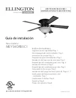
Page 1: ...paration pg 3 Hanging Bracket Installation pg 3 Fan Assembly Step One pg 4 Wiring pg 4 Fan Assembly Step Two pg 5 Blade Assembly pg 5 Light Kit Assembly Optional pgs 6 7 Testing Your Fan pg 7 Troubleshooting pg 8 Parts Replacement pg 8 Warranty pg 8 READ THESE INSTRUCTIONS AND SAVE THEM FOR FUTURE USE Installation Guide For Model MEY54ORB5C1 E206035 ...

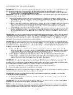
Page 2: ...12 gauge or there is more than one house wire to connect to the corresponding fan lead wires consult an electrician for the proper size wire connectors to use 5 Electrical diagrams are for reference only Light kits that are not packed with the fan must be CUL Canada or UL USA listed and marked suitable for use with the model fan you are installing Switches must be CUL Canada or UL USA general use ...

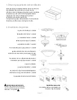
Page 3: ...ng plate pre attached to switch housing 1 piece l hardware packs c a f h required bulbs 3 x 40 watt max candelabra base bulbs included b d g e Carefully open the packaging Remove items from Styrofoam inserts Remove motor housing and place on carpet or Styrofoam to avoid damage to finish Do not discard fan carton or Styrofoam inserts should this fan need to be returned for repairs Check against par...

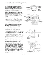
Page 4: ...rews spring washers and flat washers provided with new or original outlet box Pull wires from outlet box through center hole in mounting plate diagram c Note It is very important that you use the proper hardware when installing the mounting plate as this will support the fan page 3 ON OFF ON OFF 3 Installation Preparation This fan can be mounted as a flushmount on a regular no slope ceiling only D...

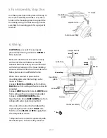
Page 5: ...iliar with electrical wiring or if the house building wires are different colors than those referred to below please use a qualified electrician When fan is secured in place on the mounting plate electrical wiring can be made as follows Connect BLACK and BLUE wire from fan to BLACK wire from ceiling with wire connector provided Connect WHITE wire from fan to WHITE wire from ceiling with wire conne...

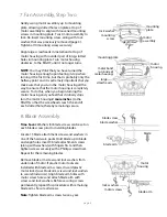
Page 6: ... you feel that it initially stops turn the motor housing 2 more inches to the RIGHT so that the screwheads reach the end of each slotted hole thereby remaining secure 8 Blade Assembly Time Saver Washers for blade screws can be set on each blade screw prior to installing blades Locate 15 blade attachment screws and washers in one of the hardware packs Hold blade up to blade and align holes Insert 3...

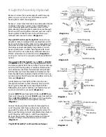
Page 7: ...op of light kit fitter Remove finial finial plate and rubber washer from threaded rod at bottom of light kit fitter Save hex nut lock washer finial finial plate and rubber washer for later use diagram c Gently feed wires from light kit fitter one by one through center hole in switch housing Screw switch housing onto threaded rod at top of light kit fitter followed by lock washer and hex nut Tighte...

Page 8: ...ain extension for fan for light It is recommended that you test fan before finalizing installation Restore power from circuit box and light switch if applicable Test fan speeds with the pull chain on switch housing Start at the OFF position no blade movement First pull will set the fan to HI Second pull will set the fan to MEDIUM Third pull will set the fan to LOW Fourth pull will re set the fan t...

Page 9: ...orkmanship Contact Craftmade Ellington Customer Service at 1 800 486 4892 to arrange for return of fan Return fan shipping prepaid to Craftmade Ellington We will repair or ship you a replacement fan and we will pay the return shipping cost 5 YEAR WARRANTY CRAFTMADE ELLINGTON will repair or replace at no charge to the original purchaser any fan motor that fails to operate satisfactorily when failur...

Page 10: ...entilador Pág 2 Inventario de piezas Pág 2 Preparación para la instalación Pág 3 Instalación del soporte de montaje Pág 3 Ensamblaje del ventilador paso uno Pág 4 Instalación eléctrica Pág 4 Ensamblaje del ventilador paso dos Pág 5 Colocación de las aspas Pág 5 Instalación del juego de luz opcional Págs 6 7 Verificación del funcionamiento del ventilador Pág 7 Localización de fallas Pág 8 Garantía ...

Page 11: ... del cable de la casa es superior al 12 o hay más de un cable de la casa para conectar a los cables principales del ventilador al cual corresponda cada uno consultar con un electricista para informarse sobre el tamaño correcto de conectores para cable que se debe usar 5 Los diagramas eléctricos son únicamente para referencia Los juegos de luz que no se incluyen con el ventilador deben tener el sím...

Page 12: ...s de artículos de ferretería página 2 1 Desempaquetado del ventilador Abrir el empaque cuidadosamente Sacar los artículos del embalaje Sacar el motor y ponerlo en una alfombra o en el embalaje para evitar rayar el acabado Guardar la caja de cartón o el empaquetamiento original en caso de que tenga que mandar el ventilador para alguna reparación Comprobar las piezas del ventilador con el inventario...

Page 13: ...uitar el aparato existente ADVERTENCIA Si utiliza una caja de salida existente asegurarse de que la caja de salida esté firmemente conectada a la estructura del edificio y que sea capaz de sostener el peso total del ventilador Asegurarse de que la caja de salida indique claramente que Sirve para ventilador FOR FAN SUPPORT si no se debe reemplazar con una caja de salida aprobada El no hacer el camb...

Page 14: ...ón favor de buscar un electricista calificado Una vez que el ventilador esté bien sujeto en la placa de montaje se puede hacer la instalación eléctrica como sigue Conectar el cable NEGRO y el cable AZUL del ventilador al cable NEGRO que sale del techo con un conector para cable provisto Conectar el cable BLANCO del ventilador al cable BLANCO del techo con un conector para cable provisto Conectar t...

Page 15: ...tor cabezas de tornillo grande página 5 bastidor del motor unidad del motor placa de montaje placa de montaje 8 Colocación de las aspas bastidor del motor brazo para el aspa tornillos para el brazo para el aspa arandelas de seguridad tornillo para fijar el aspa aspa arandela para fijar el aspa brazo para el aspa Para ahorrar tiempo Se pueden poner las arandelas en los tornillos que son para las as...

Page 16: ...y la arandela de hule de la varilla roscada en la parte inferior del conectador para el juego de luz Guardar la tuerca hexagonal la arandela de seguridad el adorno con rosca la placa del adorno con rosca y la arandela de hule para uso más adelante diagrama c Con cuidado pasar los cables del conectador para el juego de luz uno por uno por el agujero de en medio de la caja de encendido Atornillar la...

Page 17: ...orno con rosca cadena de encendido para el ventilador para la luz página 7 Se le recomienda poner el ventilador a prueba antes de terminar la instalación Regresar la corriente de electricidad en el cortacircuitos y encender el interruptor de la luz en la pared si se aplica Verificar las velocidades del ventilador con la cadena de encendido en la caja de encendido Empezar en estado de APAGADO sin m...

Page 18: ...terior con las siguientes condiciones GARANTIA DE 1 AÑO CRAFTMADE ELLINGTON reemplazará o reparará cualquier ventilador que tenga funcionamiento deficiente debido a defectos en los materiales o trabajo manual Comunicarse con el Servicio al cliente de CRAFTMADE ELLINGTON al 1 800 486 4892 para acordar el reenvío del ventilador Devolver el ventilador con los gastos de envío propagados a Craftmade El...

Reviews: