background image

page 8

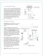
Remove 3 screws from switch housing cap.

If you wish to use fan WITHOUT the light kit

, align 

holes in switch housing cap with holes in switch 
housing. Use screws that were just removed to 
attach switch housing cap to switch housing. 

Please 

proceed to Section 11 on page 9 to complete 
installation.

If you wish to use fan WITH the light kit

, punch 

center cap out of switch housing cap with a 
screwdriver.

IMPORTANT: 

Any light kit purchased for use with this 

fan 

MUST be CUL/UL-APPROVED for WET 

LOCATIONS or OUTDOOR USE.

Locate 

BLACK

 (or 

BLUE

) and 

WHITE

 wires in switch 

housing labeled LIGHT. Remove and discard plastic 
that holds these 2 wires together. 

Remove hex nut and lock washer from threaded rod 
at top of light kit fitter. Gently feed wires from light 
kit fitter through center hole in switch housing cap 
and then screw switch housing cap onto threaded 
rod.

["Light Kit Assembly" continued on next page.]

10. Light Kit Assembly (Optional).

hex nut

lock washer

motor 
housing

switch housing

switch
housing
cap

center cap

light kit fitter

9. Switch Housing Assembly.

Remove 1 screw from switch housing plate 
(on underside of motor) and loosen the other 
2 screws. Align slotted holes at top of switch 
housing with loosened screws in switch 
housing plate, allowing the male plug from 
the motor housing to come through hole in 
middle of switch housing. Twist switch 
housing to lock. Re-insert screw that was just 
removed and securely tighten all 3 screws 
with a Phillips screwdriver.

Connect male plug from motor housing to 
female plug from switch housing. Be sure that 
the plugs connect completely.

motor housing

switch housing

switch

housing

cap

switch housing

plate

male plug

female plug

threaded rod

Summary of Contents for POM52ABZ5

Page 1: ...pg 3 Fan Assembly pgs 4 5 Wiring pg 6 Canopy Assembly pg 7 Blade Assembly pg 7 Switch Housing Assembly pg 8 Light Kit Assembly Optional pgs 8 9 Testing Your Fan pg 9 Troubleshooting pg 10 Warranty pg...

Page 2: ...oper size wire connectors to use WARNING If using this fan in a WET or DAMP location this fan must be connected to a supply circuit that is protected by a Ground Fault Circuit Interrupter GFCI to redu...

Page 3: ...nging ball with pin and clip 1 piece d motor housing 1 piece e weatherproof hanging ball cover 1 piece f blade arm 5 pieces g canopy cover 1 piece h switch housing 1 piece i switch housing cap 1 piece...

Page 4: ...bracket to outlet box using original screws spring washers and flat washers provided with new or original outlet box If installing on a vaulted ceiling face opening of hanging bracket towards high poi...

Page 5: ...prepare for threading electrical wires through downrod apply a small piece of electrical tape to the ends of the electrical wires this will keep the wires together when threading them through the down...

Page 6: ...safety cable length by loosening screw and nut on the safety cable vice and pulling on the cable Adjust slack in cable to a hands length and secure vice by tightening screw and nut securely Refer to...

Page 7: ...is secured in place on the hanging bracket electrical wiring can be made as follows Connect BLACK and BLUE wire from fan to BLACK wire from ceiling with wire connector provided Connect WHITE wire from...

Page 8: ...k washers to secure blade arms Align blade arm holes with motor screw holes and attach blade arm with lock washers and blade arm screws Before securing screws permanently repeat procedure with remaini...

Page 9: ...es from light kit fitter through center hole in switch housing cap and then screw switch housing cap onto threaded rod Light Kit Assembly continued on next page 10 Light Kit Assembly Optional hex nut...

Page 10: ...Troubleshooting section to solve any issues before contacting Customer Service Important While it is necessary to lift the cover on the reverse switch to operate the reverse switch DO NOT remove weath...

Page 11: ...any fan which has faulty performance due to a defect in material or workmanship Contact Craftmade Ellington Customer Service at 1 800 486 4892 to arrange for return of fan Return fan shipping prepaid...

Page 12: ...a cubierta decorativa P g 7 Colocaci n de las aspas P g 7 Instalaci n de la caja de encendido P g 8 Instalaci n del juego de luz opcional P gs 8 9 Verificaci n del funcionamiento del ventilador P g 9...

Page 13: ...r con un electricista para informarse sobre el tama o correcto de conectores para cable que se debe usar ADVERTENCIA Si va a utilizar este ventilador en un lugar MOJADO o HUMEDO hay que conectar el ve...

Page 14: ...unidad e cubierta a prueba de la intemperie para la bola que sirve para colgar 1 unidad f brazo para el aspa 5 unidades g tapa de la cubierta decorativa 1 unidad h caja de encendido 1 unidad i cubiert...

Page 15: ...un techo abovedado colocar el soporte de montaje con la abertura dirigida hacia la parte alta del techo Arreglar el alambrado el ctrico los cables en la parte de atr s del soporte y lejos de la abertu...

Page 16: ...ncia Para preparar los cables para pasarlos por el tubo poner un pedacito de cinta aisladora en la punta de los cables esto mantendr los cables juntos al pasarlos por el tubo Aflojar los tornillos de...

Page 17: ...olgarlo Volver a poner el seguro en el cable de seguridad y ajustar el largo del cable de seguridad aflojando el tornillo y la tuerca del seguro del cable Ajustar la parte floja del cable para que mid...

Page 18: ...ez que el ventilador est bien sujeto en el soporte de montaje se puede hacer la instalaci n el ctrica como sigue Conectar el cable NEGRO y el cable AZUL del ventilador al cable NEGRO que sale del tech...

Page 19: ...para el aspa Alinear los agujeros de uno de los brazos para las aspas con los agujeros para los tornillos en el motor y fijar el brazo para el aspa con arandelas de seguridad y tornillos para el brazo...

Page 20: ...ego de luz Con cuidado pasar los cables del juego de luz por el agujero de en medio de la cubierta de la caja de encendido y luego atornillar la cubierta de la caja de encendido en la varilla roscada...

Page 21: ...estado de APAGADO sin movimiento de las aspas Con el primer tir n el ventilador estar en marcha ALTA El segundo tir n pondr el ventilador en marcha MEDIA El tercer tir n bajar el ventilador a marcha...

Page 22: ...LLINGTON CRAFTMADE ELLINGTON garantiza este ventilador al comprador original de grupo familiar para uso interior con las siguientes condiciones GARANTIA DE 1 A O CRAFTMADE ELLINGTON reemplazar o repar...

Reviews: