


page 6
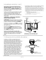
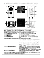
IN ORDER TO WIRE WALL CONTROL
, remove
existing wall switch.
Wire the WALL CONTROL
with wire connectors provided
as shown in
diagram at right.
* Wrap each wire connector separately with
electrical tape as an extra safety measure.
Gently push wires and taped wire connectors
into outlet box.
WARNING! CONNECT WIRES IN THE
FOLLOWING ORDER ONLY!
WARNING
: Turn off circuit breakers to current
fixture from breaker panel and be sure switch
is turned to the
OFF
position.
Connect
GREEN
ground wired to ground from
house or directly to one of the screws from the
outlet box.
Connect one
BLACK
wire from wall control to
BLACK
(hot) lead wire from house. Connect
second
BLACK
wire from wall control to
BLACK
load wire to fan.
Attach wall control to outlet box and secure
with screws from original wall switch. Attach
front plate to wall control using 2 screws
provided with the wall control.
black (OUT to fan)
green
black
(AC IN from
breaker box)
black
(TO POWER supply)
(wiring for wall control)
black
green/
green/
bare
bare
ground
ground
green/
bare
ground
outlet box
wall
control
plate
Modifications not approved by the party responsible for compliance
could void the user's authority to operate the equipment.
*NOTE: This equipment has been tested and found to comply with the limits for a Class B
digital device, pursuant to Part 15 of the FCC Rules. These limits are designed to provide
reasonable protection against harmful interference in a residential installation. This
equipment generates, uses and can radiate radio frequency energy and, if not installed and
used in accordance with the instructions, may cause harmful interference to radio
communications. However, there is no guarantee that interference will not occur in a
particular installation. If this equipment does cause harmful interference to radio or television
reception, which can be determined by turning the equipment off and on, the user is
encouraged to try to correct the interference by one or more of the following measures:
* Reorient or relocate the receiving antenna.
* Increase the separation between the equipment and receiver.
* Connect the equipment into an outlet on a circuit different from that to which the
receiver is connected.
Consult the dealer or an experienced radio/TV technician for help.
6. Wiring. (cont.)
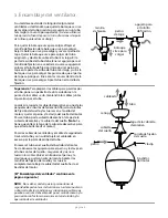
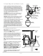
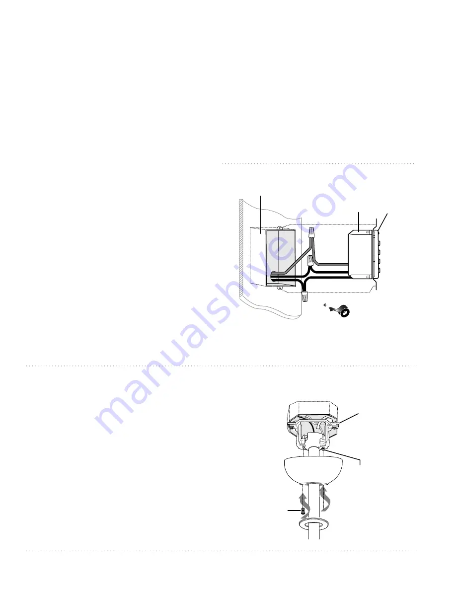
7. Canopy Assembly.
Locate 2 screws on underside of hanging
bracket and remove screw closest to the open
end of the hanging bracket. Partially loosen the
other screw. Lift canopy to hanging bracket.
Place rounded part of slotted hole in canopy
over loosened screw in hanging bracket and
push up. Twist canopy to lock. Re-insert screw
that was removed and then tighten both
screws securely. Slide canopy cover up to
canopy, aligning rounded part of slotted holes
in canopy cover with screwheads in bottom of
canopy. Turn canopy cover to the right
(clockwise) until it stops.
hanging
bracket
canopy
screw
screw
canopy cover


