background image

Tube Tugger   

11

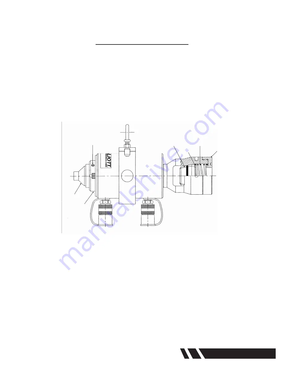
TOOL CHANGEOVER

Changing the Nosepiece:

1.  Loosen socket screws in nosepiece adapter with Allen wrench.
2.  Remove nosepiece from nosepiece adapter.
3.  Insert new nosepiece into nosepiece adapter.
4.  Make sure that the socket screw engages into slotted ring of the nosepiece.
5.  Tighten socket screw to lock in nosepiece.

Changing the Collet Set:

6.  Engage spanner wrench into threaded cap and loosen cap.
7.  Unthread cap from rear of Tube-Tugger.
8.  Remove compression spring and thrust washer.
9.  Remove set of collet jaws from Tube-Tugger.
10.  Lubricate new set of collet jaws on the OD of the jaws.
11.  Insert new set of collet jaws into Tube-Tugger.
12.  Insert thrust washer and compression spring.
13.  Thread cap onto Tube-Tugger.
14.  Secure cap firmly using spanner wrench and release fork.

TABLE OF CONTENTS

Introduction ......................................................................2 
Safety...............................................................................3 
Start-up ............................................................................4 
Quick Reference Diagram................................................5 
Operation ......................................................................6-7 
Tool Changeover .............................................................8 
Tool Selection Guide / Specifications ..............................9 

TOOL CHANGEOVER

Changing The Nosepiece: 

1. 

Loosen socket screws in nosepiece adapter with Allen wrench. 

2. 

Remove nosepiece from nosepiece adapter. 

3. 

Insert new nosepiece into nosepiece adapter. 

4. 

Make sure that the socket screw engages into slotted ring of the nosepiece. 

5. 

Tighten socket screw to lock in nosepiece. 

Changing The Collet Set: 

Thrust Washer 

Collet Set 

Diagram E

Socket Screw 

Nosepiece 

Nosepiece 

Adapter 

Threaded Cap

Compression Spring 

1. 

Engage spanner wrench into threaded cap and loosen cap. 

2. 

Unthread cap from rear of Tube-Tugger. 

3. 

Remove compression spring and thrust washer. 

4. 

Remove set of collet jaws from Tube-Tugger. 

5. 

Lubricate new set of collet jaws on the OD of the jaws. 

6. 

Insert new set of collet jaws into Tube-Tugger. 

7. 

Insert thrust washer and compression spring. 

8. 

Thread cap onto Tube-Tugger. 

9. 

Secure cap firmly using spanner wrench and release fork. 

  Page 8 

Elliott Tube-Tugger 

TM-36 

TM-36 

Elliott Tube-Tugger 

Page 1 

Summary of Contents for Tube Tugger

Page 1: ...www elliott tool com Tube Pipe Cleaners Tube Testers Tube Plugs Tube Removal Tube Installation Tube Tugger Semi Continuous Tube Extractor Operating and Maintenance Instructions ...

Page 2: ......

Page 3: ...er 3 Table Of Contents Introduction 4 Safety Instructions 5 Start Up 7 Quick Reference Diagram 8 Operating Instructions 9 Tool Changeover 11 Tool Selection Chart Specifications 12 Troubleshooting 14 Warranty 15 ...

Page 4: ...rchase welcome to our company our products are our ambassadors If this is a repeat purchase you can rest assured that the same value you have received in the past will continue with all of your purchases now and in the future The Tube Tugger has been designed for the following types of equipment Chillers Heat Exchangers Fin Fan Coolers Surface Condensers If you have any questions regarding this pr...

Page 5: ...ere appears to be damage to the machine if screws are loose or missing or if performance appears to be unsatisfactory 10 Never use the Tube Tugger or any other power tool when under the influence of medication drugs or alcohol that decrease concentration and impair operator control 11 DO NOT attempt to adjust or service the rod end relief valve on a double acting cylinder or ram If oil leakage is ...

Page 6: ...and possibly cause personal injury 16 Keep the cylinder clean at all times While at a job site when the cylinder is not in use keep the piston rod fully retracted and upside down 17 Use an approved high grade pipe thread sealant to seal all hydraulic connections PTFE tape can be used if only one layer of tape is used and it is applied carefully two threads back to prevent the tape from being pinch...

Page 7: ...ally in contact with female fitting shoulder on the tube pulling cylinder before threading down the locking fitting Otherwise the cylinder s relief valve will activate and release a fog of hydraulic fluid and the cylinder will remain idle 4 Before operating the pump all hose connections must be tightened with the proper tools Do not overtighten Connections should only be tightened securely and lea...

Page 8: ... Screw M8 x 1 25 x 12 Nosepiece Adapter 16 130207 Screw In Holder Base 16 130208 Release Fork 16 130206 Thrust Washer P1067AE Compression Spring 16 170303 Threaded Cap 16 181005 Spanner Wrench 16 120022 Hydraulic Cylinder 17RH303 Collet Holder Adapter Package 16 130210 Nosepiece Adapter 16 130207 Diagram A Counter Balance Eye Bolt Bracket Assembly 80RH303 1 Operator Side Handles Seal Kit 17 300077...

Page 9: ...th an impact drive or by hand NOTE Be careful not to impact the spear too deep as this will cause difficulty in extracting the tubes 5 Secure Tube Tugger to counter balance 6 Position the Tube Tugger over the spear and hold against the tube sheet 7 Initiate the stroke of the Tube Tugger When the Tube Tugger has reached its maximum stroke initiate the return stroke keeping the Tube Tugger in contac...

Page 10: ...ube Tugger OPERATING INSTRUCTIONS CONT Tube Tugger in operation Diagram D Tube Tugger secured to counter balance and positioned over the spear Spear being impacted into tube TM 36 Elliott Tube Tugger Page 7 ...

Page 11: ... using spanner wrench and release fork TOOL CHANGEOVER Changing The Nosepiece 1 Loosen socket screws in nosepiece adapter with Allen wrench 2 Remove nosepiece from nosepiece adapter 3 Insert new nosepiece into nosepiece adapter 4 Make sure that the socket screw engages into slotted ring of the nosepiece 5 Tighten socket screw to lock in nosepiece Changing The Collet Set Thrust Washer Collet Set Di...

Page 12: ...7 8 9 TT875 8 TT875 8 48 0 530 13 5 0 701 17 8 10 12 TT875 10 TT875 10 48 0 592 15 0 0 750 19 1 13 15 TT875 13 TT875 13 48 0 675 17 1 0 810 20 6 16 18 TT875 16 TT875 16 48 0 735 18 7 0 852 21 6 19 24 TT875 19 TT875 19 48 0 781 19 8 0 875 22 2 1 25 4mm 7 TT1000 7 TT1000 7 48 0 620 15 7 0 778 19 8 3 4 80 40125N100 80 40125C100 8 9 TT1000 8 TT1000 8 48 0 655 16 6 0 826 21 0 10 12 TT1000 10 TT1000 10 ...

Page 13: ... 940 329 0mm 15 940 405 0mm 18 250 464 0mm 80 40125 6 6 000 152 4mm 18 000 457 0mm 22 000 559 0mm Hydraulic Pumps Part Number Pump Type HP Maximum Operating Pressure psi Power Requirement Weight Repair Kit Lbs Kg M5773 00 110V Electric 10 000 25 Amps 110V 88 39 9 17 300332 M5776 00 220V Electric 15 Amps 220V M5775 00 Pneumatic 3 50 cfm 80 psi 91 41 3 80 36102D3 Manual NA 10 000 NA 28 12 7 17 30050...

Page 14: ...ct but pump achieves full pressure Hose connector not properly seated or pressurized Disconnect hoses relieve pressure in hoses by depressing ball into a rag on floor To relieve pressure in female connector insert wooden dowel into fitting wrap a rag around connector and tap with a hammer ...

Page 15: ...anufacturer s warranty to Seller Seller shall not be liable for any damages or delays caused by defective material or workmanship No allowance will be made for repairs or alterations made by others without Seller s written consent or approval If repairs or alterations are attempted without Seller s consent Seller s warranty is void THE WARRANTIES PROVIDED IN THE OBLIGATIONS AND LIABILITIES OF SELL...

Page 16: ...1 800 332 0447 Fax 1 937 253 9189 www elliott tool com Printed in the USA 08 2018 Elliott Tool Technologies Ltd TM 36 PL 8 Elliott Tool offers a complete line of precision tube tools to meet your needs Contact us or your local support Contact Us www elliott tool com support Locally Supported By ...

Reviews: