Connections and Indicators
| 21 of 157
Ellisys USB Explorer 350
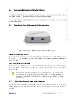
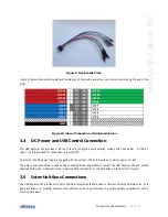
Figure 7 Type-C Adapter
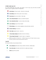
Off
Near zero voltage on CC. The CC line is floating when neither UFP nor DFP are
attached. When only the UFP is attached, the LED remains off as this attachment
provides a pull-down that is not recognized by the adapter circuitry.
Orange
5V (or near 5V), indicating the DFP alone is attached.
Green
Indicates a valid connection voltage (cRd-Connect, 0.25V..2.04V).
3.3
Logic Connector
The logic connector exposes 20 pins (2 rows of 10 pins each) spaced at 1.27mm x 1.27mm. A ground is provided
along with 16 input/output pins. There are two unused pins. This connector may also be used for adapting to Type-
C or USB Power Delivery implementations using the supplied Type-C adapter and associated flat cable.
CC Line Logic Capture
Pin 15 is dedicated for logic capture of the CC line (this can be enabled in the
Recording Options
menu). When the
flat cable is used, all other logic inputs are precluded from use.
Summary of Contents for USB Explorer 350
Page 1: ...Ellisys USB Explorer 350 User Manual Version 0 83 October 30 2015...
Page 36: ...36 of 157 Exerciser User Interface User Guide Figure 13 Source Capabilities Interface...
Page 41: ...Exerciser User Interface 41 of 157 Ellisys USB Explorer 350 Figure 16 Edit VDM Modes...
Page 61: ...Examiner User Interface 61 of 157 Ellisys USB Explorer 350 Figure 31 Examiner Settings Tab...
Page 86: ...86 of 157 Managing Analyzer Recordings User Guide...
Page 138: ...138 of 157 Analyzer Protocol Error Verifications User Guide...
Page 157: ......


