22 of 157 |
Connections and Indicators
User Guide
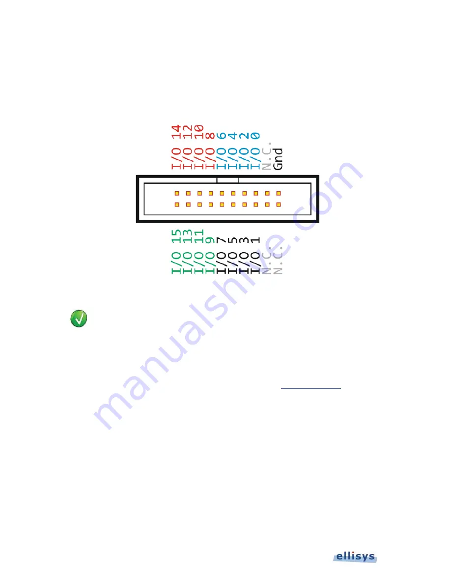
GPIO Placement on Logic Connector
The general-purpose inputs and outputs (GPIOs) can be used for logic signal capture (up to 16 signals) and to
control the capture process (start, stop, or pause the capture). Enabling logic signals capture or other Logic
Connector inputs is explained in Figure 8 below illustrates the layout of the pins on the USB Explorer 350 Logic
Connector.
Figure 8 Pin Layout for Logic Connector
In some cases, USB Power Delivery signaling (CC) and related GND may be applied directly to
this connector for Analyzer capture (without use of the custom cable or adapters). GND and I/O
15 are reserved for this purpose.
In these cases, control of resistors Rp and Rd are left to the control of the user and are not
controlled by the USB Explorer 350 or the associated Type-C adapter. To prevent a false detect
by the device attached, the user may need to install a series resistor on the CC input ranging
between 9K Ohms and 20K Ohms. Contact Ellisys for support (
support@ellisys.com
).
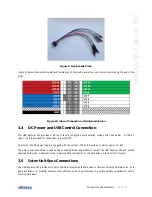
Flying Leads Probe
A Flying Leads probe is provided to connect to the Logic Connector. Captured logic signals are displayed in the
Instant Timing
view and are captured concurrently with other types of traffic. This probe includes a polarized plug
that attaches to the Logic Connector on the side of the USB Explorer 350, with loose wires (female sockets) wires on
the other end.
Summary of Contents for USB Explorer 350
Page 1: ...Ellisys USB Explorer 350 User Manual Version 0 83 October 30 2015...
Page 36: ...36 of 157 Exerciser User Interface User Guide Figure 13 Source Capabilities Interface...
Page 41: ...Exerciser User Interface 41 of 157 Ellisys USB Explorer 350 Figure 16 Edit VDM Modes...
Page 61: ...Examiner User Interface 61 of 157 Ellisys USB Explorer 350 Figure 31 Examiner Settings Tab...
Page 86: ...86 of 157 Managing Analyzer Recordings User Guide...
Page 138: ...138 of 157 Analyzer Protocol Error Verifications User Guide...
Page 157: ......

