Analyzer – Setting Up
| 79 of 157
Ellisys USB Explorer 350
9.
Analyzer – Setting Up
Various settings are available to control how bus traffic and events are captured, whether any traffic is filtered from
the Analyzer’s memory, when a capture should start and end, and various other settings that configure the Analyzer
to properly record traffic in accordance with the user’s preferences and expected bus characteristics.
9.1
Analyzer Hardware Setup – Type-C
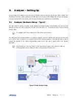
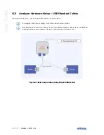
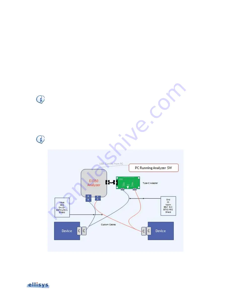
The basic setup for taking a recording involves placing the Analyzer between communicating two ports, such as
between a device and a host or between a Provider and a Consumer, etc. This is shown below in Figure 33 Basic
Analyzer Setup.
The supplied 24VDC Power Supply is not shown below but is required.
The USB Explorer 350 is placed between two system components, such as a USB host and device, and is connected
over a USB 3.1 Gen 1 connection to a computer that hosts the Analyzer application. This USB connection is used to
program the Analyzer for the capture characteristics desired by the user, and to upload traffic to the Analyzer
application.
Note that the use of the word “Device” in the figure below is generic (these may be a USB host,
a USB peripheral, a Power Delivery Provider, a Power Delivery Consumer, etc.).
Figure 33 Basic Analyzer Setup
Summary of Contents for USB Explorer 350
Page 1: ...Ellisys USB Explorer 350 User Manual Version 0 83 October 30 2015...
Page 36: ...36 of 157 Exerciser User Interface User Guide Figure 13 Source Capabilities Interface...
Page 41: ...Exerciser User Interface 41 of 157 Ellisys USB Explorer 350 Figure 16 Edit VDM Modes...
Page 61: ...Examiner User Interface 61 of 157 Ellisys USB Explorer 350 Figure 31 Examiner Settings Tab...
Page 86: ...86 of 157 Managing Analyzer Recordings User Guide...
Page 138: ...138 of 157 Analyzer Protocol Error Verifications User Guide...
Page 157: ......


