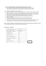
Paper Oil filled ( PILC)
0.50 to 0.56
2Cross linked poly ( XPLE)
0.52 to 0.58
Jelly filled poly
0.64
Polyethylene ( PIC)
0.67
PTFE ( Teflon)
0.71
Paper (Pulp 0.083 uf/mile)
0.72
Paper (Pulp 0.072 uf/mile)
0.88
Foam Poly
0.82
Air space Coaxial
0.94
Air
0.98
4.2 FAULT LOCATION ON CABLES WITH KNOWN PROPAGATION VELOCITY FACTOR
In many cases, the cable layout and characteristics are known and the fault location and
analysis should be simple and quick. Under these conditions, the procedure is as follows:
(1) Disconnect the faulty pair from service if possible.
(2) Connect the faulty pair to the line terminals of the tester. (3) Press the 'ON’ key to power up the tester.
(4) After the initialisation period set the required propagation velocity factor by means of the arrow keys
when in PVF Mode. Listed in Table A. are typical values of propagation velocity factor for various cable
dielectrics. Use the menu select key to select metres or feet for the cursor value.
(5) Inspect the trace for a fault pulse and reduce to the minimum Range where the fault
pulse is clearly visible.
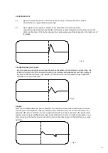
(6) Change to locate mode and operate the cursor keys to position the cursor line at
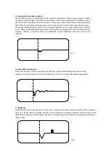
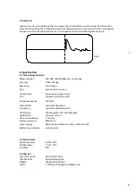
the start of the break point of the fault pulse , for example trace as shown in Fig.1
(7) The distance to the fault may now be read directly from the cursor value, which is at the bottom centre
of the LCD display. This reading can be in meters or feet depending on the parameter selected.
NOTE: The test lead length is automatically removed to give a direct reading of the cable length, therefore
the test leads supplied with the instruments must always be used.
Dielectric Type Typical PVF
Table A
4.


