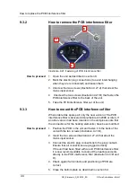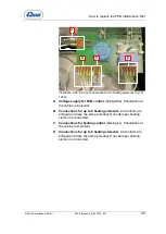
How to replace the PCB control
32
SM_Elmasonic_S_02.2018_EN
© Elma Schmidbauer GmbH
8.3
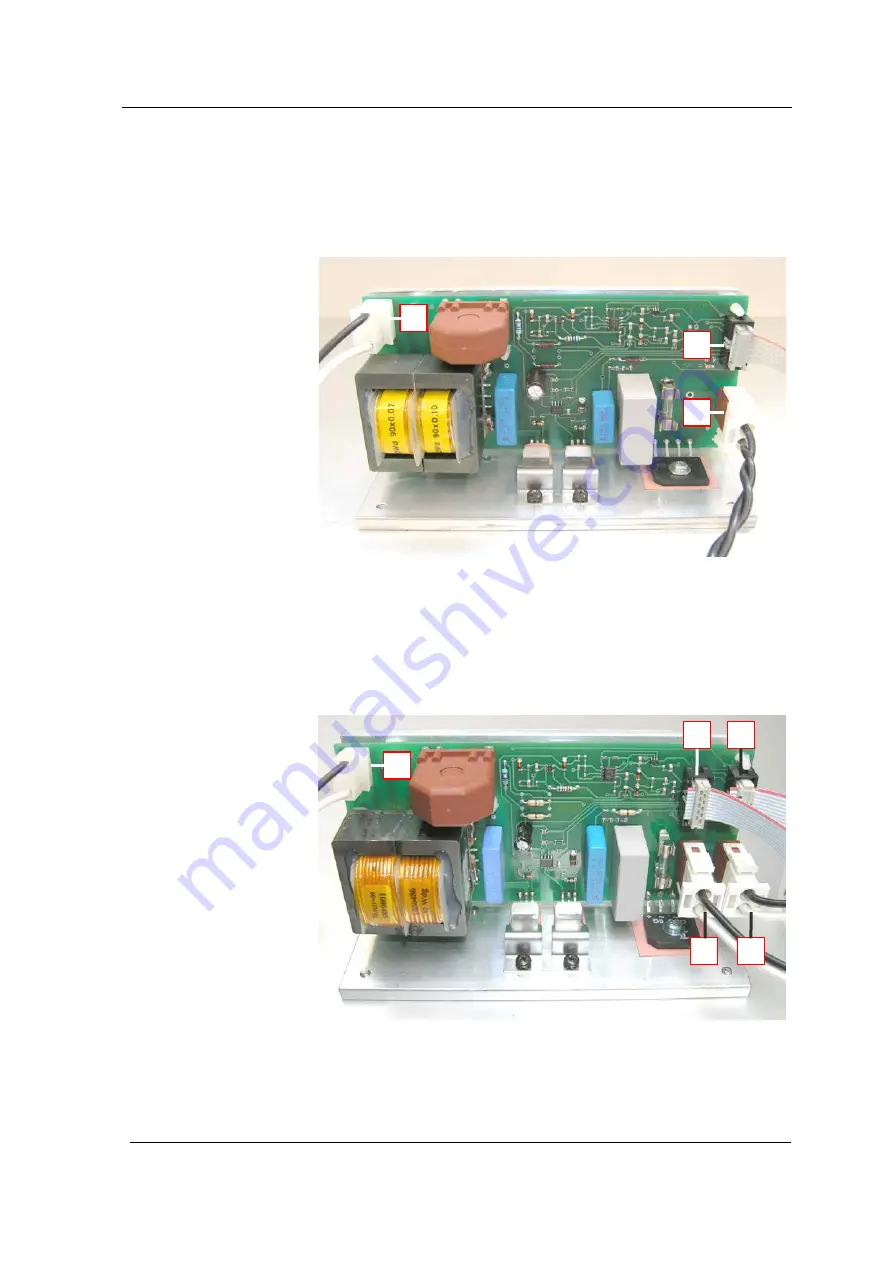
Power module S350R | S450H | S500HM | S900H
On these units the power end stage is arranged on a separate
PCB, the power module. The S350 R | S S 900 H is fitted with 2
power modules. They are parallel connected to the mains
voltage and the PCB control.
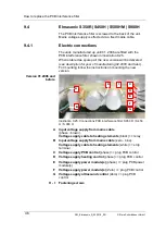
Illustration 8.6. Connections PCB power module S 450 H or slave
power module on S 350 R | S 900 H
Connection transducer systems
(high frequency).
Connection control line
connection to control PCB.
S 900 H: connecting to master power module.
Mains voltage supply power module
S 350 R / S 900 H: connecting to master power module.
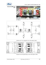
Illust. 8.7. Connections of the master power module on S350R|S900H
Connection control line
to slave power module (on S350 R|
S900 H).
Voltage supply PCB
connection to slave power module
(on S 350 R | S 900 H).
A
B
C
D
E
A
B
C
A
C
E
D
B


