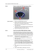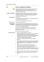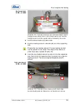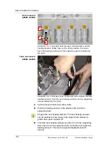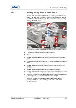
How to replace the PCB interference filter
© Elma Schmidbauer GmbH
SM_Elmasonic_S_02.2018_EN
43
9.3
Elmasonic S 120 (H) – S 300 (H)
The PCB interference filter is screwed to the back of the unit.
The mains input socket is soldered to the PCB interference filter
and must be replaced with the PCB.
9.3.1
Electric connections
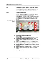
The units manufactured in 10.2005 or before are fitted with the
PCB interference filter illustrated below.
When ordered as a spare part the new version will be delivered
(
see description for year of manufacturing 11. 2005 or later
).
For mounting follow the instructions on mounting the new
version.
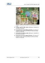
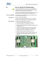
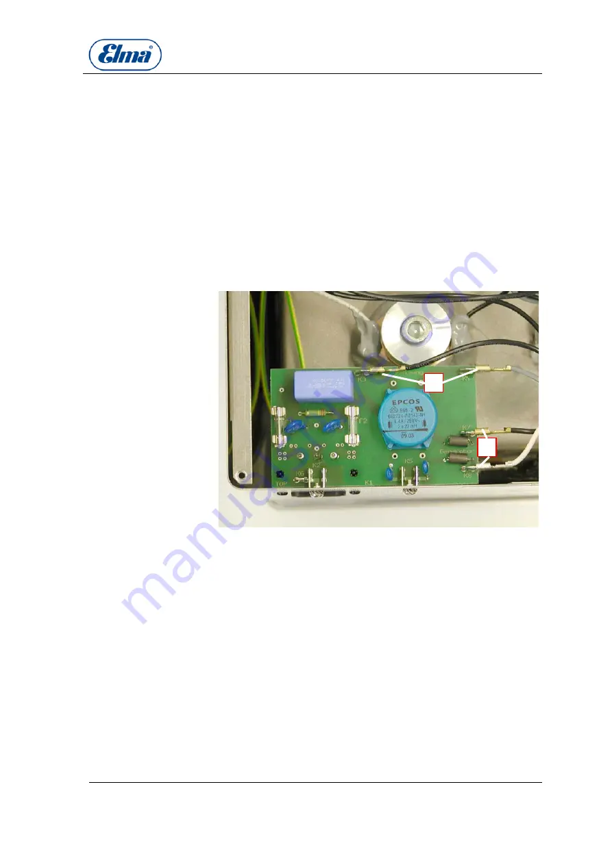
Illustration 9.20. Connections PCB interference filter
Connections for heating element
(mains voltage). The
heating elements are connected to plug distribution contacts.
Polarization of the cables is irrelevant.
Connections to PCB control
(mains voltage). Polarization of
the cables is irrelevant.
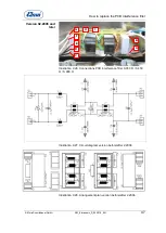
The modification on the PCB interference filter is relevant
only for units with heating.
On this PCB there is a separate plug contact for each electric
heating connection.
On units with more than one heating element, the heating
elements were connected with separate plug distributors up
until 10.2005. This is no longer necessary.
It is now easier to leave the plug distributors unused and to
connect each cable on on of the connections indicated in
illustration 9.23.C and D
.
Versions
115 V before 10.2005
230V before 10.2006
A
B
Versions
115 V 11.2005 and later
230V 10.2006 and later
A
B


