How to replace the PCB interference filter
46
SM_Elmasonic_S_02.2018_EN
© Elma Schmidbauer GmbH
9.4
Elmasonic S350R | S450H | S500HM | S900H
The PCB interference filter is screwed to the back of the unit.
Mains voltage supply is effected via a fixed mains cable.
9.4.1
Electric connections
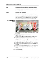
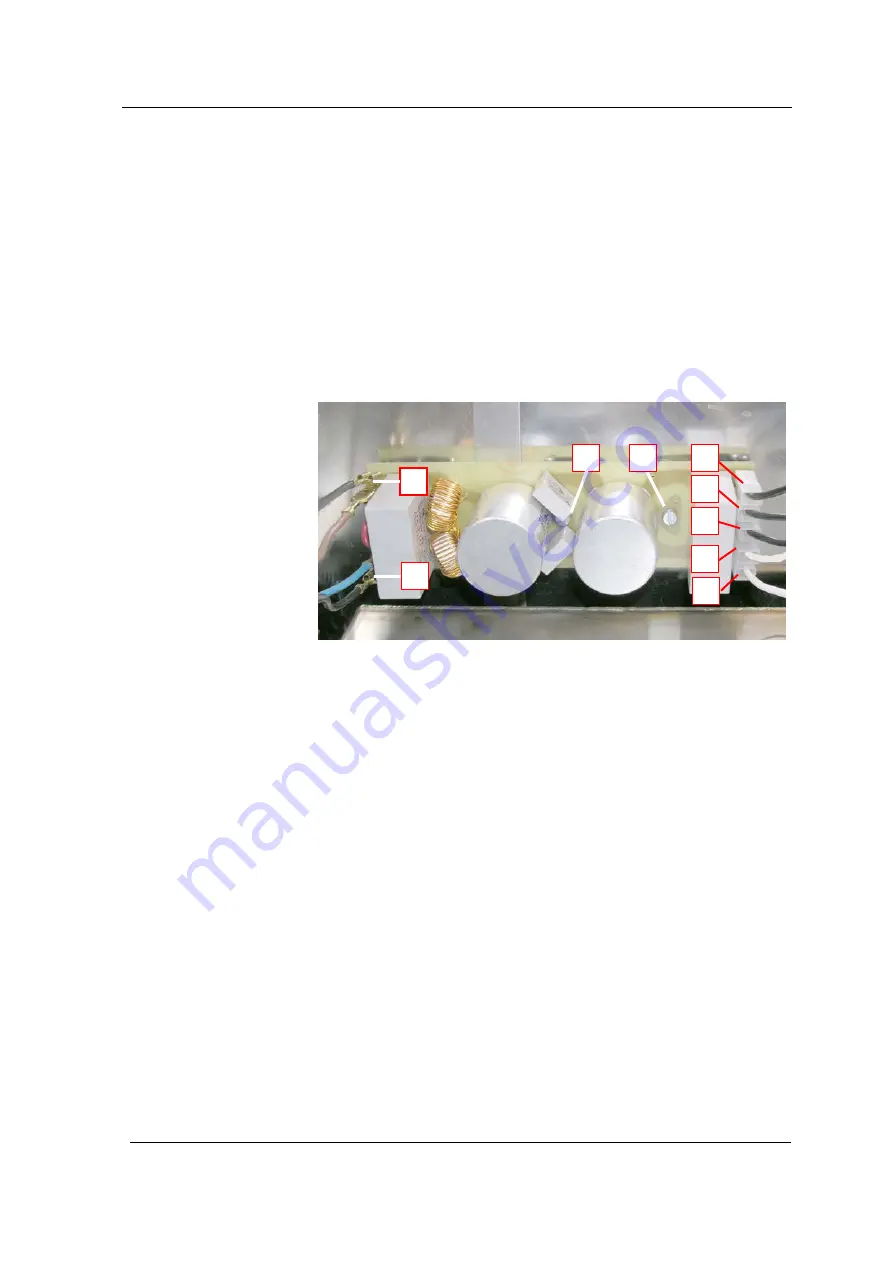
The units manufactured up until 01. 2006 are fitted with the
PCB interference filter shown in illustration 9.25.
When ordered as spare part the new version will be delivered
(
see description for year of manufacturing 02.2006 and later
).
For mounting follow the instructions on mounting the new
version.
Illustration 9.25. Connections PCB interference filter S 350 R | S 450
H / S 900 H
Input voltage supply from mains cable
(phase - brown).
Voltage supply cable to heating elements
(black) >> relay
Input voltage supply from mains cable
(zero - blue).
Voltage supply cable to heating elements
(white) >> strip
terminal
Voltage supply PCB control
(phase) >> plug PCB control
Voltage supply heating control
(phase) >> plug PCB control
Voltage supply power module(s)
(phase) >> plug PCB power
module(s)
Voltage supply power module(s)
(Zero) >> plug PCB control
Voltage supply ultrasound control
(Zero) >> plug PCB
control
Fastening screws
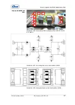
Version 01.2006 and
before
A
B
C
D
E
F
G
H - I
A
D
B
C
H
G
F
E
I


