background image


Initial operation


© Elma GmbH & Co KG 

BA/Elmasteam/GB/0306 

15

4.3 

Mounting flexible hand piece (option) 

Ensure that the Elmasteam is switched off. Then proceed as 
follows: 

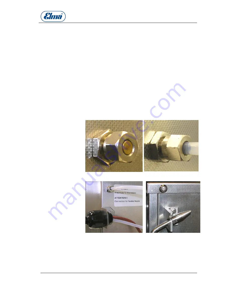
1.  Open and remove the blind screw on the back of the unit 

(

Illustration 4.4

) with a fork wrench (wrench size14 mm).  

Mounting flexible

nozzle

2.  Remove the fixed nozzle from the unit front (if available). 

Close the outlet with the blind screw removed in step 1. 

3.  Position the union nut of the tube connection to the 

connection duct. (

Illustration 4.5

4.  Rescrew and tighten the union nut do not jam the nut.  

5.  Check if the nut is correctly tightened. 

6. 

Mount the supporting angle for the tube (

illustration 4.6

).


7.  Mount the supporting angle for the hand piece 

(

illustration 4.7

). 


Illustration 4.4 Connection with        Illustration 4.5 Mounted fixed blind 
screw                                                nozzle 

Illustration 4.6 angle support tube      Illustration 4.7 angle support 


Summary of Contents for Elmasteam 10

Page 1: ...Operating Instructions High performance steam jet cleaner Elmasteam GB english ...

Page 2: ...11 1 Flexible hand piece 13 4 Initial operation 13 4 1 Placement and ambient conditions 13 4 2 Mounting of fixed nozzle with foot activated switch option 14 4 3 Mounting flexible hand piece option 15 4 4 Filling of the unit Filling by hand 16 4 5 Automatic filling 16 4 6 Connection pump Aquamatic 17 5 Handling during operation 18 5 1 Working with the hand piece 19 5 2 Working with the fixed nozzle...

Page 3: ...tioning of the unit The present steam jet cleaner has been designed for the cleaning of items only Do not steam clean living beings Intended use After unpacking check the unit for possible transport damages In case of visible damages do not put the unit into operation Contact your supplier and forwarding agent Check for transport damages For safety reasons the present unit must be connected to a c...

Page 4: ...matic No chemical additions Carry out the maintenance works at regular intervals as described in the present Operating Instructions in order to guarantee the correct functioning of the unit and to keep the safety standard see section 7 Repair must be carried out by authorized specialized personnel only Pull the mains plug before opening the unit In case of damage or faulty operation please contact...

Page 5: ...arge for the safe cleaning of small items Order no 376 073 0000 C Sieve small for the safe cleaning of small items Order no 376 072 0000 D Collecting tank for the controlled steam collection Order no 376 070 0000 E Transport cart for Elmasteam 5 and 10 Order no 376 080 0000 F 3 2 CE conformity The present Elmasteam steam jet cleaner is in compliance with the CE marking criteria and the following E...

Page 6: ...ng modes Elmasteam 10 on the left steam compressed air and on the right steam compressed air if compressed air connection is available or on the left hot water and on the right steam compressed air if compressor air connection is available 3 4 Functioning In a safety pressure vessel filled by hand or automatically the water is heated by means of a powerful heating element up to a temperature of 17...

Page 7: ...ants Outlet Elmasteam 3 flling by hand filling funnel variant A fixed nozzle with foot activated switch Elmasteam 5 automtic filling pump Aquamatic variant B flexible hand piece connection for external compressed air inlet Elmasteam 10 Operating modes Elmasteam 3 and 5 steam compressed air Elmasteam 10 steam compressed air hot water ...

Page 8: ...ses A 115V 230V 20 10 16 16 Protection class IP 20 IP 20 IP 20 Pressure in vessel bar 8 8 8 Pressure vessel volume litre 3 5 10 Max filling volume litre 2 6 4 5 9 0 Steam temperature at outlet approx 160 C approx 160 C approx 160 C Housing dimensions W x D x H mm 300 x 305 x 315 300 x 305 x 405 288 x 305 x 615 Units overall dimensions W x D x H mm 300 x 410 x 330 300 x 410 x 430 300 x 410 x 640 Ho...

Page 9: ...steam discharge device in case of improper opening of the closing screw cap of the tank 3 8 Elements top view A B D Illustration 3 1 Unit top view C screw cap of filling opening for manual filling A filling bead collecting basin for overflow water B handles C ventilation slits D 3 9 Elements front view Elmasteam 3 B Elmasteam 5 A C D E Illustration 3 2 Operating elements Elmasteam 3 5 F ...

Page 10: ... manometer B Indication of the steam pressure in the tank bar As soon as the pressure reaches 8 bar the unit is ready for operation see E Steam volume control at outlet C For the stepless regulation of the steam volume at the steam outlet nozzle between 0 and 100 Visual indicator lamp ready D Is turned on as soon as the operating pressure of the tank is reached and the unit is ready for operation ...

Page 11: ... Elma GmbH Co KG BA Elmasteam GB 0306 11 3 10 Elements back view Elmasteam 3 Elmasteam 5 A F B D C G H Illustration 3 4a Elmasteam 3 5 back view Elmasteam 10 A A B B C C D E F G H Illustration 3 4b Elmasteam 10 back view ...

Page 12: ... automatic water supply pump Aquamatic and outlet duct for emptying of the tank H 3 11 Functioning of the fixed nozzle The connection socket for the fixed nozzle is on the front of the unit see illustration 3 1 For mounting the fixed nozzle and the foot activated switch please follow the instructions given in section 4 2 Mounting The foot activated switch controls the steam outlet at the fixed noz...

Page 13: ...on the right can be operated with hot water too B A C Illustration 3 6 Flexible hand piece 4 Initial operation 4 1 Placement and ambient conditions Check the Elmasteam for possible transport damages before initial operation Check for transport damages In case of visible damages do not connect the unit to the mains Contact your supplier and forwarding agent immediately Place the unit in a dry and s...

Page 14: ... unit to the mains 4 2 Mounting of fixed nozzle with foot activated switch option Ensure that the Elmasteam is switched off Then proceed as follows 1 Open and remove the blind screw on the front of the unit illustration 3 2 C illustration 4 2 by means of a fork wrench wrench size14 mm Mounting of fixed nozzle 2 Position the fixed nozzle precisely rectangular onto the connecting duct illustration 4...

Page 15: ...nit front if available Close the outlet with the blind screw removed in step 1 3 Position the union nut of the tube connection to the connection duct Illustration 4 5 4 Rescrew and tighten the union nut do not jam the nut 5 Check if the nut is correctly tightened 6 Mount the supporting angle for the tube illustration 4 6 7 Mount the supporting angle for the hand piece illustration 4 7 Illustration...

Page 16: ...tering the housing Fill the water carefully avoid overfilling Keep the water from entering the ventilation slits in the unit covers CAUTION Fill in the water slowly Ensure that only the required quantity is filled see section 3 6 Technical details tank capacity Any water surplus is collected in the filling bead and must be wiped off Filling of tank Close the screw cap Close the screw cap If any wa...

Page 17: ...t 15 μSiemens The pump requires a minimum pressure of 2 bar at the inlet NOTE Ensure that the Elmasteam is switched off Mounting 1 Connect the pump supply duct illustration 4 8 B to the water supply you need a tube of the required length Connect the tube between the pump supply duct and the adapter piece of the water tap by means of hose clamps Please ensure a secure and safe fixing of the hose 2 ...

Page 18: ...Handling during operation For reasons of safety the steam cleaner must be operated by authorized and correctly instructed personnel only Authorized personnel Risk of scalding by hot steam Unauthorized third persons must not keep within reach of the steam jet during operation of the unit Ensure your own safety Be careful when the steam outlet is activated Avoid hazardous situations caused by uninte...

Page 19: ...ection Distance to steam outlet 5 1 Working with the hand piece Risk of static chargeing of the hand piece during steam operation Hold the hand piece so that you are in permanent contact with the grounding contact see C illustration 3 6 on the side of the hand piece The electric charge that might be created is not dangerous CAUTION Activate the steam function by pressing the red left key on the ha...

Page 20: ... air too The cleaning item can be dried with compressed air Follow up drying 6 Cleaning options 6 1 Operation with hot water Elmasteam 10 only On the Elmasteam 10 the outlet on the left either flexible hand piece or fixed nozzle can be operated with hot water This alternative operating mode is optional and must be requested on ordering the unit so that the steam cleaner can be manufactured accordi...

Page 21: ...ifyer or other chemicals into the unit For decalcification use water only CAUTION The unit must be coold down before decalcification can be carried out depressurize the unit The tank should be filled above minimum level Preliminary 1 Screw the maintenance tube M included in delivery to the ball valve illustration 3 4 H How to proceed 2 Switch the unit on and let it heat up 3 Observe the pressure i...

Page 22: ...et the unit cool down depressurize the unit and empty the tank Preliminary A Illustration 8 1 Unit bottom view 1 Lay the unit on left side How to proceed 2 Open the drain plug illustration 8 1 A e g with a fork wrench 14 mm 3 Screw the angle piece of the maintenance tube J included in delivery onto the thread of the drain opening shut the ball valve on the other end of the tube 4 Direct the free e...

Page 23: ...he lime 10 Wait until the tank is completely empty 11 Lay the unit on ist left side again and remove the maintenance tube 12 Wrap teflon tape around the thread of the drain screw in order to make it tight Then fix the screw back into the drain outlet 7 3 Repair Should any repair works be necessary please contact your supplier or the manufacturer of the unit Repair works must be carried out by spec...

Page 24: ...ing stations or returned to the manufacturer 9 Manufacturer s contact address Elma Hans Schmidbauer GmbH Co KG Kolpingstr 1 7 D 78224 Singen Phone 49 0 7731 882 0 Fax 49 0 7731 882 266 info elma germany com e mail www elma germany com Homepage Technical Support Phone 49 0 7731 882 280 Fax 49 0 7731 882 253 support elma germany com e mail ...

Reviews: