Adjustment of the generators
© Elma GmbH & Co KG
SM/Transsonic_LC/1104/D
101
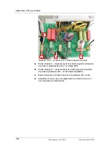
Illustration 16.7.1. Generator print: adjustment measuring points
Probe channel 1 – measurement of collector signal (connection
of probe at upper connection of collector resistance).
Probe channel 2 – measurement of emitter signal (connection
of probe at right measuring point. Caution: do not connect to
transistor connection: faulty measuring result).
Mass connection probe channel 2 (connection of probe at left
measuring point. Caution: do not connect to transistor
connection: faulty measuring result).
Adjustment coil for carrying out adjustment: turn ferrite core out
or in (according to instructions).
Illustration 16.7.2. Adjustment coil, latest model. Older units can be
equipped with adjustment coils of the former model. The model of the
coil has no influence on the functioning of the unit.
A
C
B
D
A
B
C
D
Summary of Contents for LC130H
Page 2: ......


