background image


12                                                      Manual Version: 1.0                                                       


3.3. USB 2.0 Connector


3.3.1 USB 2.0 M/B Pin 


3.3.2 USB 2.0 M12 Pin 


Pin Assign and Definition 

M/B 

Pin No. 

M12 

Pin No. 

Description 

VCC 

USB D- 

USB D+ 

GND 

SHELL 

BRAID 


Summary of Contents for HMI-C170H3CS4

Page 1: ...1 Manual Version 1 0 MS 9Z08 HMI C170H3CS4 Waterproof Panel PC User Manual...

Page 2: ...TOR 11 3 2 1 LAN M B Pin 11 3 2 2 LAN M12 Pin 11 3 3 USB 2 0 CONNECTOR 12 3 3 1 USB 2 0 M B Pin 12 3 3 2 USB 2 0 M12 Pin 12 3 4 SERIAL PORT 13 3 4 1 Serial M B Pin 13 3 4 2 Serial M12 Pin 13 4 TROUBLE...

Page 3: ...f the product s Before setup and usage of the product s please read through this manual thoroughly 2 The specifications shall apply only to the product s in this manual 3 The specifications may be mod...

Page 4: ...4 Manual Version 1 0...

Page 5: ...0H3CS4 Machine Accessory Package Driver CD Power Supply Kit choose one of below DC IN Power cord M12 Adapter x1 AC IN M12 Power cord x1 M12 LAN1 x1 M12 USB2 0 x2 M12 RS 232 x1 COM1 If any items are mi...

Page 6: ...6 Manual Version 1 0 1 Appearance Front View Back View Side View L Side View R M12 Connector Type Stand alone Circular Type...

Page 7: ...7 Manual Version 1 0 2 System Installation 2 1 Dimensions...

Page 8: ...8 Manual Version 1 0 2 2 Power Control Button Button Function Power on off HDD LED Power LED Reset Reset Power on off...

Page 9: ...I O Definition 3 1 Power Connector 3 1 1 DC IN M B Pin 3 1 2 DC IN M12 Pin Pin Assign and Definition M B Pin No M12 Pin No Description 1 1 12V DC 2 2 12V DC 3 3 GND 4 4 GND Pin 1 Pin 3 Pin 2 Pin 4 Pi...

Page 10: ...10 Manual Version 1 0 3 1 3 AC IN Adapter Pin 90 3 1 4 AC IN M12 Pin Pin Assign and Definition M B Pin No M12 Pin No Description 1 1 E 2 2 N 3 3 L N L 1 2 3...

Page 11: ...Manual Version 1 0 3 2 LAN RJ45 Connector 3 2 1 LAN M B Pin 3 2 2 LAN M12 Pin Pin Assign and Definition M B Pin No M12 Pin No Description 1 6 TX1 2 4 TX1 3 5 TX2 4 1 TX3 5 8 TX3 6 7 TX2 7 2 TX4 8 3 T...

Page 12: ...anual Version 1 0 3 3 USB 2 0 Connector 3 3 1 USB 2 0 M B Pin 3 3 2 USB 2 0 M12 Pin Pin Assign and Definition M B Pin No M12 Pin No Description 1 1 VCC 2 2 USB D 3 3 USB D 4 4 GND SHELL 5 BRAID 5 1 4...

Page 13: ...erial Port 3 4 1 Serial M B Pin 3 4 2 Serial M12 Pin Pin Assign and Definition M B Pin No M12 Pin No Description RS 232 1 1 DCD 2 2 RXD 3 3 TXD 4 4 DTR 5 5 GND 6 6 DSR 7 7 RTS 8 8 CTS 9 9 N A N A 10 N...

Page 14: ...t down It is best to shut down your computer using the Shut Down icon in the operating system Using other methods including those listed below may result in data failure If the Shut Down procedure doe...

Page 15: ...Manual Version 1 0 System monitor shows no display 1 Check if the system is connected to an electrical outlet and is turned on 2 The system may be in Standby mode Press any key to activate the Displa...

Page 16: ...GbE LAN Mini PCIe 2 x Full size Mini PCIe1 Slot w NANO SIM Holder Mini PCIe2 Slot w mSATA SATA 1 x 2 5 HDD SSD Default 128GB SSD mSATA 1 Shared with Mini PCIe2 RJ 45 1 USB 2 x USB 2 0 Serial 1 x COM C...

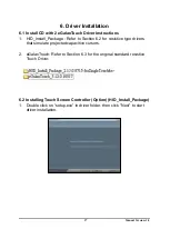
Page 17: ...to Section 6 2 for resistive type drivers that simulate projected capacitive cursors 2 eGalaxTouch Refer to Section 6 3 for the original standard resistive Touch Driver 6 2 Installing Touch Screen Co...

Page 18: ...18 Manual Version 1 0 2 Click Browse and Select another folder and Click Next 3 Click Next to continue...

Page 19: ...19 Manual Version 1 0 4 Click Next to continue 5 Wait for the setup program to complete copying files This includes USB COM interface drivers...

Page 20: ...1 0 6 Click Finish to continue Prior to re starting computer save any software or files 7 After rebooting please click on the desktop HIDeGalaxTouch 8 Check if the interface detected in the figure mat...

Page 21: ...calibration The calibration screens will appear as follows User should follow the guide to touch and hold the blinking symbol in the calibration window until it shows OK to make sure that the utility...

Page 22: ...22 Manual Version 1 0 10 Calibration is complete...

Page 23: ...Touch Utility 1 General tools properties page This page includes 4 point testing Draw test and advanced tools 2 Advanced tools properties page This page can clear calibration records and perform 9 poi...

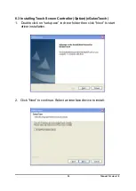
Page 24: ...n 1 0 6 3 Installing Touch Screen Controller Option eGalaxTouch 1 Double click on setup exe in driver folder then click Next to start driver installation 2 Click Next to continue Select an interface d...

Page 25: ...25 Manual Version 1 0 3 Click Next to continue 4 Click Next to continue...

Page 26: ...26 Manual Version 1 0 5 Click OK to continue 6 Click Next to continue...

Page 27: ...27 Manual Version 1 0 7 Click Browse and Select another folder and Click Next 8 Click Next to continue...

Page 28: ...28 Manual Version 1 0 9 Click Next to continue 10 Wait for the setup program to complete copying files also includes USB COM interface...

Page 29: ...tallation for this new found device The calibration screens will appear as follows User should follow the guide to touch and hold the blinking symbol in the calibration window until it shows OK to mak...

Page 30: ...uch utility shows all eGalax Touch screen controllers installed as shown below including USB or RS 232 2 Tools Property Page Calibration draw test tools and the linearity curve of the touch screen wer...

Reviews: