


Note 1: 80 MHz and 800 MHz, the higher frequency range applies.
Note 2: These guidelines may not apply in all situations. Electromagnetic propagation is affected by absorption and reflection from structures,objects and people.
a. Field strengths from fixed transmitters, such as base stations for radio (cellular/cordless) telephones and land mobile radios, amateur radio,AM and FM radio
broadcast and TV broadcast cannot be predicted theoretically with accuracy. To assess the electromagnetic environment due to fixed RF transmitters, an
electromagnetic site survey should be considered. If the measured field strength in the location in which the device is used exceeds the applicable RF
compliance level above, the device should be observed to verify normal operation. If abnormal performance is observed, additional measures may be
necessary, such as re-orienting or relocating the device.
b. Over the frequency range 150 kHz to 80 MHz, field strengths should be less than 3 V/m.
c. Calibration for current injection clamps shall be performed in a 150 Ω system.
d. If the frequency stepping skips over an ISM or amateur band, as applicable, an additional test frequency shall be used in the ISM or amateur radio band.
This applies to each ISM and amateur radio band within the specified frequency range.
e. Applicable to ME EQUIPMENT and ME SYSTEMS with RATED input current less than or equal to 16 A / phase and ME EQUIPMENT and ME SYSTEMS
with RATED input current greater than 16 A / phase.
For transmitters rated at a maximum output power not listed above, the recommended separation distance in metres (m) can be estimated using the equation
applicable to the frequency of the transmitter, where P is the maximum output power rating of the transmitter in watts (W)according to the transmitter manufacturer.
Note 1: At 80 MHz and 800 MHz, the separation distance for the higher frequency range applies.
Note 2: The ISM (industrial, scientific and medical) bands between 0,15 MHz and 80 MHz are 6,765 MHz to 6,795 MHz; 13,553 MHz to 13,567 MHz; 26,957 MHz
to 27,283 MHz; and 40,66 MHz to 40,70 MHz. The amateur radio bands between 0,15 MHz and 80 MHz are 1,8 MHz to 2,0 MHz, 3,5 MHz to 4,0 MHz, 5,3 MHz
to 5,4 MHz, 7 MHz to 7,3 MHz, 10,1 MHz to 10,15 MHz, 14 MHz to 14,2 MHz, 18,07 MHz to 18,17
MHz,21,0 MHz to 21,4 MHz, 24,89 MHz to 24,99 MHz, 28,0 MHz to 29,7 MHz and 50,0 MHz to 54,0 MHz.
Note 3: These guidelines may not apply in all situations. Electromagnetic propagation is affected by absorption and reflection from structures,objects and people.
Note: If necessary to achieve the IMMUNITY TEST LEVEL, the distance between the transmitting antenna and the ME EQUIPMENT or ME SYSTEM may
be reduced to 1 m. The 1 m test distance is permitted by IEC 61000-4-3.
a. For some services, only the uplink frequencies are included.
b. The carrier shall be modulated using a 50 % duty cycle square wave signal.
c. As an alternative to FM modulation, 50 % pulse modulation at 18 Hz may be used because while it does not represent actual modulation, it would be worst case.
The MANUFACTURER should consider reducing the minimum separation distance, based on RISK MANAGEMENT, and using higher IMMUNITY TEST
LEVELS that are appropriate for the reduced minimum separation distance. Minimum separation distances for higher IMMUNITY TEST LEVELS shall be
calculated using the following equation:
E= 6 / d √ P
Where P is the maximum power in W, d is the minimum separation distance in m, and E is the IMMUNITY TEST LEVEL in V/m.
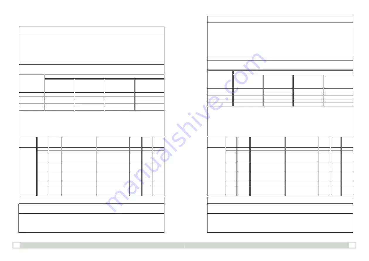
The device is intended for use in an electromagnetic environment in which radiated RF disturbances are controlled. The customer or the user of the device
can help prevent electromagnetic interference by maintaining a minimum distance between portable and mobile RF communications equipment (transmitters)
and the device as recommended below, according to the maximum output power of the communications equipment.
Recommended separation distances between portable and mobile RF communications equipment and the device
Rated
maximum output
power of transmitter
(W)
150 kHz to 80 MHz
(out ISM and amateur
radio bands)
d= 1.2 √ P
150 kHz to 80 MHz
(out ISM and amateur
radio bands)
d= 0.6 √ P
80 MHz to 800 MHz
d= 1.2 √ P
800 MHz to 2.7 GHz
d= 2.3 √ P
0,01
0,1
1
10
100
0,12
0,38
1,2
3,8
12
0,06
0,19
0,6
1,9
6
0,12
0,38
1,2
3,8
12
0,23
0,73
2,3
7,3
23
Separation distance according to frequency of transmitter(m)
Radiated RF
Test
Frequency
(MHz)
Band a)
(MHz)
Service a)
Modulation b)
Modu-
lation b)
(W)
Distance
(m)
Immunity
Test
Level(V/m)
385
450
710
745
780
810
870
930
1720
1845
1970
2450
5240
5240
5785
380-390
380-390
704-787
800-960
1700-1990
2400-2570
5100-5800
TETRA 400
GMRS 460, FRS 460
LTE BANDI 13, 17
GSM 800
/
900, TETRA 800,
İ
DEN 820, LTE Bant 5
GSM 1800, CDMA 1900,
GSM 1900,
DECT, LTE Bant1,3,4,25, UMTS
Bluetooth,WLAN 802.11b
/
g
/
n,
RFID 2450,LTE Bant 7
WLAN 802.11a
/
n
Pulse modulation b) 18 Hz
FM c) ± 5 kHz deviation 1 kHz sine
Pulse modulation b) 217 Hz
Pulse modulation b) 18 Hz
Pulse modulation b) 217 Hz
Pulse modulation b) 217 Hz
Pulse modulation b) 217 Hz
1,8
2
0,2
2
2
2
0,2
0,3
0,3
0,3
0,3
0,3
0,3
0,3
27
28
9
28
28
28
9
IEC61000-4-3
(Test
specifications
for
ENCLOSURE
PORT
IMMUNITY to
RF
wireless
communica-
tions
equipments
Kıl
avuz ve ima
l
a
tçının bil
diri
mi-
e
l
ek
troman
yetik
b
a
ğışı
k
lı
k
Bu cihaz a
ş
a
ğıd
a belirtilen elektromanyetik ortamda kullan
ı
lmak amac
ı
yla tasarlanm
ıştır.
Bu cihaz mü
ş
terisi ya da kullan
ı
c
ı
s
ı
bu gibi ortamlarda kullan
ı
l
dığın
dan emin
olmal
ıdı
r.
Not 1: 80 MHz ve 800 MHz’de, daha yüksek olan frekans aral
ığı
geçerlidir.
Not 2: Bu yönergeler her ko
ş
ulda geçerli olmayabilir. Elektromanyetik yay
ı
lma; binalar, nesneler ve insanlar taraf
ın
dan emilim ve yans
ıtı
lmadan etkilenir.
a. Telsiz (cep
/
kablosuz) telefonlar ve mobil araç telsizleri, amatör telsiz, AM ve FM radyo yay
ın
l
arı
ve TV yay
ını
gibi sabit vericilerden gelen alan güçleri, teorik
aç
ıd
an önceden do
ğru o
larak tahmin edilemez. Sabit RF vericileri nedeniyle elektroman yetik ortam
ı
de
ğ
erlendirmek için bir elektromanyetik yer incelemesi
dü
ş
ünülmelidir. Bu cihaz
ın
kullan
ı
l
dığı
yerdeki ölçülen alan gücü, yuk
arıda
ki geçerli RF uyumluluk düzeyini bu cihaz
ın
çal
ış
mas
ını
n normal oldu
ğ
u, gözlemlene-
rek kontrol edilmelidir. Anormal bir performans gözlenirse, bu cihaz
ın
yönünü veya yerini de
ğ
i
ş
tirmek gibi ilave önlemler gerekebilir.
b. 150 kHz ila 80 MHz aras
ın
daki frekans aral
ığı
üzerindeki alan güçlerinin 3 V
/
m’den az olmas
ı
gerekir.
c. Ak
ı
m enjeksiyon kelepçelerinin kalibrasyonl
arı, 1
5
0Ω
sistemde yap
ı
lmal
ıdı
r.
d. E
ğ
er frekans atlamal
arı I
SM veya amatör bantl
arı at
l
ı
yor ise, ISM ve amatör radyo bantl
arını
kapsayan ek test frekansl
arı
kullan
ı
lmal
ıdı
r. Bu frekanslar, her
ISM ve amatör radyo bantl
arını
kapsayacak
ş
ekilde belirtilen frekans aral
ığı
nda uygulanmal
ıdı
r.
e. Giri
ş
anma ak
ı
m
ı,
faz ba
şın
a 16 A’e e
ş
it ve dü
ş
ük cihazlar ve giri
ş
anma ak
ı
m
ı
faz ba
şın
a 16 A’den yüksek medikal cihazlar için uygulan
ı
r.
Yukar
ı
daki listede yer almayan maksimum ç
ı
k
ış
gücü ölçülen vericiler için vericinin frekans
ı
na uygun denklem kullan
ı
larak önerilen ay
ı
rma mesafesi metre (m)
cinsinden hesaplanabilir; burada verici üreticisi taraf
ı
ndan verilen watt (W) cinsinden maksimum verici ç
ı
k
ış
gücü oran
ı
n
ı
göstermektedir.
Not 1: 80 MHz ve 800 MHz’de, daha yüksek frekans aral
ığı
için olan ay
ı
rma mesafesi uygulan
ı
r.
Not 2: 150 kHz ile 80 MHz aras
ı
ndaki ISM (endüstriyel, bilimsel ve t
ı
bbi) bantlar
ı
6.765 MHz ile 6.795 MHz; 13.553 MHz ile 13.567 MHz; 26.957 MHz ile 27.283
MHz ve 40.66 MHz ile 40.70 MHz’dir. 150 kHz ile 80 MHz aras
ı
ndaki amatör radyo bantlar
ı
1.8 MHz ile 2.0 MHz, 3.5 MHz ile 4.0 MHz, 5.3 MHz ile 5.4 MHz, 7
MHz ile 7.3 MHz, 10.1 MHz ile 10.15 MHz, 14 MHz ile 14.2 MHz, 18.07 MHz ile 18.17 MHz, 21.0 MHz ile 21.4 MHz, 24.89 MHz ile 24.99 MHz, 28.0 MHz ile
29.7 MHz ve 50.0 MHz ile 54.0 MHz’dir.
Not 3: Bu yönergeler her ko
ş
ulda geçerli olmayabilir. Elektromanyetik yay
ı
lma; binalar, nesneler ve insanlar taraf
ı
ndan emilim ve yans
ı
t
ı
lmadan etkilenir.
Not: BA
Ğ
I
Ş
IKLIK TEST SEV
İ
YES
İNİ
elde etmek gerekli ise, verici anten ile medikal cihaz veya medikal ekipman aras
ın
daki mesafe 1 m’ye kadar
dü
ş
ürülebilir. 1’m test mesafesi IEC 61000’e göre 1 mt test mesafesi izin verilir.
a. Baz
ı
servisler için yal
nı
zca gönderim frekansl
arı da
hil edilmi
ş
tir.
b. Ta
şı
y
ı
c
ı
sinyali; %50 duty cycle’a sahip kare dalga sinyali ile modüle edilmi
ş
tir.
c. FM modülasyonuna alternatif olarak, 18 Hz de %50 darbe modülasyonu kullan
ı
labilir, çünkü gerçek modülasyonu temsil eden en kötü senaryoyu olu
ş
turur.
İM
ALAT
ÇI, Rİ
SK YÖNET
İMİ
NE göre minimum ay
ı
rma mesafesini azaltmay
ı
ve azal
tı
lm
ış
minimum ay
ı
rma mesafesine uygun daha yüksek BA
Ğ
I
Ş
IKLIK
TEST SEV
İ
YELE
Rİ
kullanmay
ı
dü
ş
ünmelidir. Daha yüksek BA
Ğ
I
Ş
IKLIK TEST DÜZEYLE
Rİ
için minimum ay
ı
rma mesafeleri a
ş
a
ğıd
aki denklem
kullan
ı
larak hesaplanmal
ıdı
r:
E= 6
/
d
√
P
Burada P, Watt cinsinden maksimum gücü, d ise m cinsinden minimum ayr
ı
lma mesafesini ve E, V
/
m cinsinden BA
Ğ
I
Ş
IKLIK TEST SEV
İ
YES
İNİ
göstermektedir.
Bu cihaz, yay
ı
lan RF giri
ş
imlerinin kontrol edilebild
iği
elektromanyetik ortamda kullan
ı
lmak amac
ı
yla tasarlanm
ıştı
r. Bu cihaz
ı
n sahibi veya kullan
ı
c
ı
s
ı
elektromanyetik parazitten korunmak için ta
şı
nabilir ve mobil RF ileti
ş
im ayg
ı
tlar
ı
(vericiler) ile bu cihaz aras
ı
nda, ileti
ş
im ekipman
ı
n
ı
n maksimum ç
ı
k
ışı
na
bağ
l
ı
olarak, a
şağı
da önerilen minimum mesafeyi muhafaza etmelidir.
Ta
şı
nabilir ve mobil RF ileti
ş
im ekipmanla
rı
ile bu cihaz aras
ı
nda önerilen ay
ır
ma mesafesi
Vericinin hesaplanan
maksimum ç
ı
k
ış
gücü (W)
150 kHz ile 80 MHz
(ISM ve amatör radyo
bantlar
ı
d
ışı
nda)
d= 1.2
√
P
150 kHz ile 80 MHz
(ISM ve amatör radyo
bantlar
ı
d
ışı
nda)
d= 0.6
√
P
80 MHz ile 800 MHz
d= 1.2
√
P
800 MHz ile 2.7 GHz
d= 2.3
√
P
0,01
0,1
1
10
100
0,12
0,38
1,2
3,8
12
0,06
0,19
0,6
1,9
6
0,12
0,38
1,2
3,8
12
0,23
0,73
2,3
7,3
23
Vericinin frekans
ı
na göre ay
ı
rma mesafesi (m)
Işınan RF
Test
Frekansı
(MHz)
Bant a)
(MHz)
Servis a)
Modülasyon b)
Modü-
lasyon b)
(W)
Mesafe
(m)
Bağışıklık
Test
Seviyesi
385
450
710
745
780
810
870
930
1720
1845
1970
2450
5240
5240
5785
380-390
380-390
704-787
800-960
1700-1990
2400-2570
5100-5800
TETRA 400
GMRS 460, FRS 460
LTE BANDI 13, 17
GSM 800
/
900, TETRA 800,
İ
DEN 820, LTE Bant 5
GSM 1800, CDMA 1900,
GSM 1900,
DECT, LTE Bant1,3,4,25, UMTS
Bluetooth,WLAN 802.11b
/
g
/
n,
RFID 2450,LTE Bant 7
WLAN 802.11a
/
n
Darbe Modülasyonu b) 18 Hz
FM c) ±5 kHz sapma 1 kHz Sinüs
Darbe Modülasyonu b) 217 Hz
Darbe Modülasyonu b) 18 Hz
Darbe Modülasyonu b) 217 Hz
Darbe Modülasyonu b) 217 Hz
Darbe Modülasyonu b) 217 Hz
1,8
2
0,2
2
2
2
0,2
0,3
0,3
0,3
0,3
0,3
0,3
0,3
27
28
9
28
28
28
9
IEC 61000-4-3
(RF kablosuz
haberle
ş
me
cihazlar
ı
na
kutu
bağışı
kl
ı
k test
özellikleri)
14
15


