2
Technical Support: +44(0)23 9269 6638 (option 3)
PAK200526_01B ©2016 ELMDENE INTERNATIONAL LTD
C
ONNECTIONS
I/P:
+
+12Vdc or +24Vdc from PSU O/P
-
0V from PSU O/P
O/P:
+
AuxVdc un-switched PSU O/P
-
0V output to load (Common 0v for NO, NC & Aux)
NO
Normally Open relay output (see chart below)
NC
Normally Closed relay output (see chart below)
Trigger:
+
Trigger I/P from control device (+VE or Contact)
-
Trigger I/P from control device (0V or Contact)
Warning: This unit is NOT suitable for switching 240Vac. Mains loads.
Trigger & Jumper Configurations
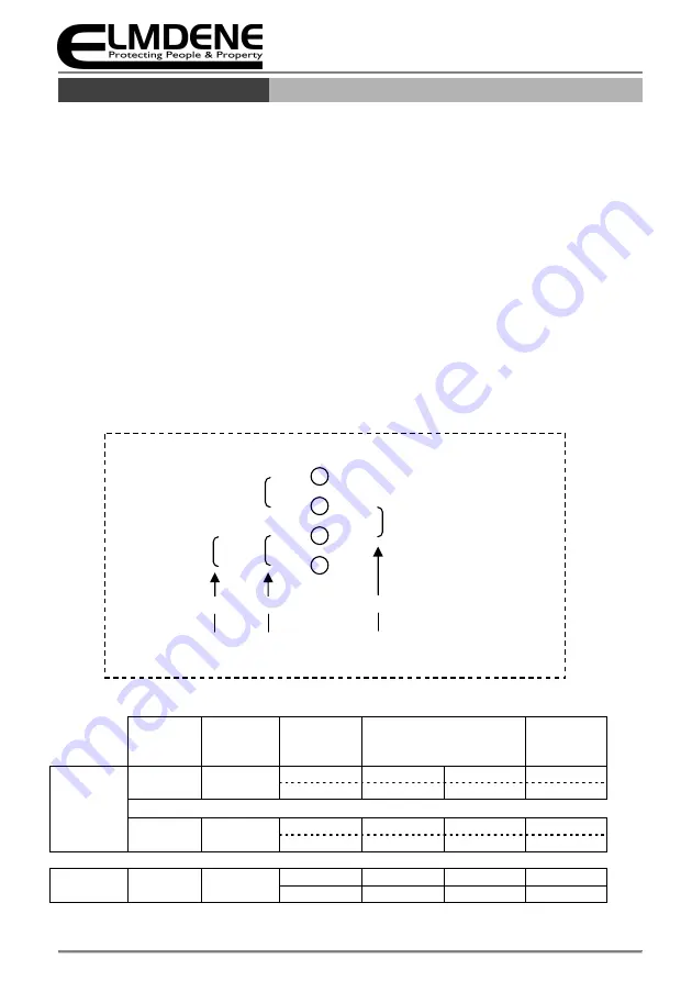
The device has 3 modes of operation set by the onboard jumpers:
•
Contact Mode (Normally Open) - Jumper across: 2 & 3
•
Contact Mode (Normally Closed) - Jumpers across: 1 & 2 and 3 & 4
•
Voltage Mode - Jumper across: 3 & 4
Table 1
defines the output state of the N.O and N.C contacts with respect to Mode selected and Trigger inputs.
Note: Trigger Input ter and - are only polarity conscious when used in Voltage mode
Table 1
Trigger
Select
Jumper(s)
Trigger
+ & -
Output
N.O N.C
LED
Contact
Mode
N.O
2 & 3
open
no output
+12/24V
OFF
closed
+12/24V
no output
ON
N.C
1 & 2
3 & 4
open
+12/24V
no output
ON
closed
no output
+12/24V
OFF
Voltage
Mode
+VE
3 & 4
removed
no output
+12/24V
OFF
applied
+12/24V
no output
ON
1
2
3
4
Trigger
Select
NO
NC
+VE
Jumper Settings for Trigger Selection
Mode:
Link Pins:
2&3
1&2
3&4
3&4


