background image

16

Operation sequence

Never operate the unit if the 
enclosure isn’t sealed.

The Main LED located in the front of the unit (as seen in Figure 1) monitors the state of the unit. All models offer the 
immediate charging mode. Models that have the Smart-Home or Smart-Pro Module can offer the controlled access 
charging mode.

IMMEDIATE CHARGING MODE

1.  Make sure that the unit has power (Main LED should be 

GREEN

)

2.  Using the Electrical Vehicle Charging Cable, connect the unit to the Electric Vehicle  

suitable SAE J1772 inlet connector.

3.  Once connected, the Main LED should light up briefly 

YELLOW

 before going to 

BLUE

.

4.  The Main LED will stay lit in the 

BLUE

 color during the charging sequence. 

5.  The Main LED will light up 

YELLOW

 once the charge is complete.

6.  When the charge is finished (or when the user wants to terminate the charge), simply disconnect the SAE J1772 

connector from the Electric Vehicle by pressing the release button on the SAE J1772 connector.

7.  Replace the Electric Vehicle Charging Cable on the supplied wall hook while making sure that the cable is coiled 

with a large enough radius to not damage the cable.

CONTROLLED ACCESS CHARGING MODE

1.  Make sure that the unit has power (Main LED should be 

GREEN

).

2.  Using the Electrical Vehicle Charging Cable, connect the unit to the Electric Vehicle suitable SAE J1772 inlet connector.
3.  Once connected, the Main LED should light up 

YELLOW

.

4.  Using a smart phone, open the EVduty mobile app (log in to your EVduty account if necessary).
5.  Choose the Station where you are located. Then select the charging station with which you want to start  

a charging session. 

6.  Click on “Start”. Charging should begin and a charging session screen sould appear containing valuable  

information such as voltage, current, power, energy, cost and duration of the session.

7.  The Main LED will stay lit in the 

BLUE

 color during the charging sequence. 

8.  The Main LED will light up 

YELLOW

 once the charge is complete.

9.  If you want to stop the charging session, simply disconnect the SAE J1772 connector from  

the Electric Vehicle by pressing the release button on the SAE J1772 connector.  
You can also press the “Stop” button in the charging session screen in the EVduty mobile app. 

10.  Replace the Electric Vehicle Charging Cable on the supplied wall hook while making sure that the cable is coiled 

with a large enough radius to not damage the cable.

Summary of Contents for EVduty EVC30 Series

Page 1: ...ELM 1013 18235 R25 EVduty User Manual ELECTRICAL VEHICLE CHARGING STATION LEVEL 2 EVC30 SERIES ...

Page 2: ...ommon problems ____________________________________________________________ 22 Diagnostic code_______________________________________________________________ 23 Contact us ______________________________________________________________________________25 Limited Warranty ________________________________________________________________________26 Figure list Figure 1 Portable model Permanent Installat...

Page 3: ...per connection of the equipment grounding conductor is able to result in a risk of electric shock Check with a qualified electrician or serviceman if you are in doubt as to whether the product is properly grounded Do not modify the plug provided with the product if it will not fit the outlet have a proper outlet installed by a qualified electrician When using electric products basic precautions sh...

Page 4: ...ase Button F SAE J1772 Electric Vehicle Connector The EVduty EVC30 series is a Level 2 Electric Vehicle Charging Station Its primary function is to send electrical power to an Electrical Vehicle that is equipped with the SAE J1772 Electric Vehicle connector Here are the main parts of the product Figure 1 Portable model Permanent Installation model Output connector ...

Page 5: ...e only available if Option 4 is 1 Output cable lenght ft 15 or 25 Output current A 16 20 24 or 30 Option 1 Option 2 Option 3 Option 4 Option 5 This charging station is offered in a variety of different models The base options choices include length of the output cable and output current There are also some other options communication module Power Input Type Input Plug Type etc The part number of t...

Page 6: ...RATING UL CSA NEMA types 3R PERSONAL PROTECTIONS Ground Monitoring Charge Circuit Interrupting Device with 20 mA threshold CCID20 DIMENSIONS LENGTH X WIDTH X DEPTH 330 mm x 165 mm x 60 mm 13 00 x 6 50 x 2 50 OUTPUT CONNECTOR SAE J1772 choice of 2 different output cable length 4 6 m 15 7 5 m 25 OPERATING TEMPERATURE 40 C to 40 C STORAGE TEMPERATURE 40 C to 80 C WEIGHT 4 5 kg 10 lbs ...

Page 7: ...e unit to a wall The wall mount bracket must be installed on a wall and fixed on a vertical stud that can support at least 4 times the weight of the unit so able to support at least 18 kg 40 lbs This device shall be mounted at a sufficient height from grade such that the height of the storage means for the coupling device is located between 600 mm 24 inches and 1 2 m 4 feet from grade B A B Insert...

Page 8: ... the charging unit station Figure 3 illustrates where the unit should be mounted for the input power cable to line up properly with the input power receptacle Holes for 1 4 screws 4x NEMA 6 50R receptacle not included Stud centerline Wall mount bracket 1 1 8 1 3 4 2 14 1 2 Figure 3 Position of the unit vs the input power receptacle ...

Page 9: ...charger The physical installation is nearly identical as the portable model see Section Installation Physical Installation Portable Model but require the unit to be locked on his wall mount bracket by installing a padlock in the hole as shown in Figure 4 Figure 4 Installation of padlock for anti theft protection Install padlock in this hole ...

Page 10: ...itable receptacle If the receptacle has to be installed consult qualified electrical personnel 2 Once the unit is receiving power the unit will do a self test During this test the Main LED will light up RED for a few seconds only Once the test is complete and everything is in good shape the Main LED will light up GREEN Permanent installation model 1 Route the input cable into a suitable junction b...

Page 11: ... mobile app go to the My terminals tab 6 Click on Add a station 7 Enter the information of the station name of the station address description optional photo optional 8 Click on Add a terminal 9 Click on Open Wi Fi Settings 10 In the settings connect to the Wi Fi network emitted by the charging station that has a name of the type EVduty EVC30 XXXXX where XXXXX represents the serial number of the c...

Page 12: ... progress To access this feature in the mobile app Go to My terminals tab In the Stations Terminals list click on the desired terminal Go to Charge tab Manage the access to the charging station The owner of a charging station may restrict access to charging station the charging station must be configured in Access Mode of type Access control and datalogging This is done by sending SMS invitations ...

Page 13: ...hare the available power according to the capacity of the protection circuit breaker that protects the power supply of the charging stations and the number of charging stations currently in use This function has two levels that can be used separately or simultaneously Level 1 is used when multiple charging stations are protected by a single circuit breaker whose capacity is between 20 A and 40 A I...

Page 14: ...el Branch circuit 40 A Main circuit 100 A Branch circuit 40 A Branch circuit 40 A Branch circuit 40 A 2 4 charging stations individually protected by 40 A circuit breakers These 4 circuit breakers are protected by a 100 A main breaker 1x Level 2 Link only Smart Home or Smart Pro Module Charging station A Charging station A Charging station C Charging station B Charging station B Charging station D...

Page 15: ...reate add a Link by configuring the following parameters Link level Value of the protection breaker Select the charging stations to link Click on Link to validate the form The charging stations in the Link will receive the configuration of the Link and will reset Main electric panel Branch circuit 40 A Main circuit 125 A Branch circuit 40 A Branch circuit 40 A Branch circuit 40 A Smart Home or Sma...

Page 16: ...e enough radius to not damage the cable CONTROLLED ACCESS CHARGING MODE 1 Make sure that the unit has power Main LED should be GREEN 2 Using the Electrical Vehicle Charging Cable connect the unit to the Electric Vehicle suitable SAE J1772 inlet connector 3 Once connected the Main LED should light up YELLOW 4 Using a smart phone open the EVduty mobile app log in to your EVduty account if necessary ...

Page 17: ...ed to the unite but the charge is not allowed right now Waiting for the vehicle to accept the charge A vehicle is connected to the unit and the battery is fully charged Blue A vehicle is connected and charging Flashing Blue A vehicle is connected and charging and the maximum output current has been configured from the EVduty mobile app to a value lower than 30 A The charging power is reduces Smart...

Page 18: ... electrical panel 2 Disconnect the charging station s input power cable either from the wall receptacle or from the junction box depending on the model and remove it from its wall mount bracket 3 Remove the six 6 screws holding the back plate to the charging station s enclosure 4 Remove the back plate 5 Using a small flat screwdriver modify the state of the DIP Switch by moving the small white lev...

Page 19: ... SWITCH POSITION 1 DIP SWITCH POSITION 2 DIP SWITCH POSITION 3 16 Right Right N A 20 Left Right N A 24 Right Left N A 30 Left Left N A Table 4 Maximum output current adjustment SW1 R4 10 DIP Switch Revision 4 10 Figure 5 Position of DIPSwitch SW1 R4 10 Output current adjustment ...

Page 20: ...SWITCH POSITION 4 6 Right Right Right N A 8 Left Right Right N A 10 Right Left Right N A 12 Left Left Right N A 16 Right Right Left N A 20 Left Right Left N A 24 Right Left Left N A 30 Left Left Left N A Table 5 Maximum output current adjustment SW5 R5 4 Figure 6 Position of DIPSwitch SW5 R5 4 DIP Switch Révision 5 4 Output current adjustment ...

Page 21: ...rs Moving and Storage The portables models of the charging station must be stored in a clean and dry location and it must be located away from any high heat sources Avoid oily or corrosive substances to contact the charging station or the power cords and plugs connectors between uses Avoid any fall or drop that can lead to impacts between a hard surface and the charging station Keep any sharp obje...

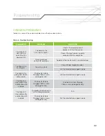
Page 22: ...r The Main LED is flashing red The unit is in fault Consult Table Diagnostic codes Call the manufacturer support service The Main LED is going from blue to yellow rapidly The Electric Vehicle Charging Cable is worn damaged or dirty Call the manufacturer support service The Main LED stays green after a connection with a vehicle The Electric Vehicle Charging Cable is worn damaged or dirty The Electr...

Page 23: ...e way it works is that the Main LED will flash RED in a certain manner and the numbers of flashes are related to a 2 digit number Here s an example 1000 ms 2500 ms 250 ms 250 ms 250 ms Diagnostic code will repeat until fault or unit is reset ms millisecond First digit 2 Second digit 3 Exemple with a diagnostic code 23 Troubleshooting ...

Page 24: ...hile charging the unit trips on a missing ground fault Unit will automatically reset after 15 mins for up to 3 retries Same as Diagnostic Code 11 23 While charging the unit trips on a ground fault 3 consecutives times Same as Diagnostic Code 11 24 While charging the unit trips on a missing ground fault 3 consecutives times Same as Diagnostic Code 11 31 Vehicle requires ventilation This charging st...

Page 25: ...25 POSTAL ADDRESS Service support Elmec 1141 2e Avenue Shawinigan Québec G9T 2X9 SERVICE SUPPORT 819 533 3888 FAX 819 533 3074 EMAIL info elmec qc ca WEBSITE elmec ca Contact us ...

Page 26: ... of similar specifications and price WHAT DOES THIS WARRANTY NOT COVER Any defect caused by an abnormal use of the product HOW TO GET SERVICE To use this warranty you must contact the Elmec Support Service and a qualified technician will verify if there is a real problem with your EVduty EVC30 Electric Vehicle Charging Station If it s the case send the EVduty EVC30 Electric Vehicle Charging Statio...

Reviews: