99
SETTING
UP
English
(3) To connect the unit with a composite video input terminal.
Connect a commercially available RCA pin plug video cable to the [VIDEO OUT] terminal
on the rear panel.
(4) To connect the PC with a USB cable.
Connect the supplied or commercially available USB cable to the [USB] terminal on the rear
panel.
N o t e
• We recommend using a USB 2.0 compliant USB cable.
• If you plug into a USB connector with the power on, the PC may not recognize this device.
• Depending on the USB environment used by the PC or peripheral equipment using
the USB 2.0 compliant cable, image transfer may be disrupted.
• Operation is not guaranteed for all environments.
N o t e
• Only one image can be output at a time; either [RGB OUT] or [VIDEO OUT]. For more
information on switching the image output, refer to "RGB/Video Switch".
• To protect the unit and peripheral devices, unplug the power plug and the AC
adapter, and turn off all other devices before connecting the video cable.
• When plugging in or unplugging the power plug, the AC adapter, or video cable, hold
the plug of the cable.
(5) To connect the AC adapter.
Connect the DC plug of the supplied AC adapter to the [DC IN 12V] terminal on the rear
panel before inserting the AC adapter in an outlet.
n
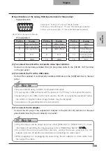
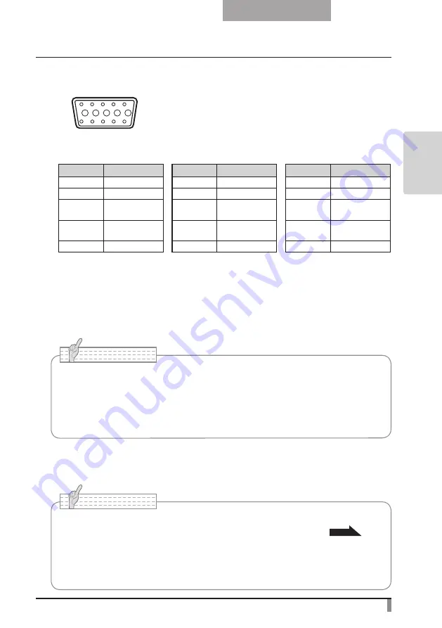
Specifications of the analog RGB input terminal of this product
Signal allocation
10
9
8
7
6
5
4
3
2
1
15 14 13
DSUB 15P shrink terminal (Female)
12 11
Video signal: Analog 0.7V (p-p) with 75
Ω
terminated
Horizontal synchronized signal: TTL level (Positive/negative polarity)
Vertical synchronized signal: TTL level (Positive/negative polarity)
Pin assignment
Pin No.
Name
Pin No.
Name
Pin No.
Name
1
Video signal (Red)
6
GND (Red)
11
GND
2
Video signal (Green)
7
GND (Green)
12
N.C
3
Video signal (Blue)
8
GND (Blue)
13
Horizontal syn-
chronized signal
4
N.C
9
N.C
14
Vertical synchro-
nized signal
5
GND
10
GND
15
N.C
Summary of Contents for L-1EX
Page 2: ......
Page 3: ......
Page 4: ......
Page 5: ...AC AC...
Page 6: ...AC AC AC AC AC AC...
Page 7: ...AC AC AC AC AC...
Page 8: ...AC AC AC AC AC AC...
Page 9: ...AC AC AC100V 50Hz 60Hz 0 40 30 85 CMOS CMOS AC FD MO MD...
Page 10: ...CD DVD LED SD Ni Cd 4...
Page 12: ...10 Manual 55 56 56 57 58 60 61 PinP 62 63 6 64 64 7 66 66 67 67 68 68...
Page 13: ...11 P 15 P 35 P 49 P 35 AF P 50 P 35 P 16 P 12 P 45 P 35 Image Mate CD ROM P 14 1...
Page 14: ...12...
Page 18: ...16 4 2 4...
Page 20: ...18 7 30 7m 30 3 0 3 0 3 0 3 0 3 0 3 0 3 0 3 0...
Page 21: ...19 OSD On Screen Display OSD OSD OSD OSD OSD 1 MENU OSD 2 MENU...
Page 22: ...20 1 2...
Page 23: ...21 Image Setting Function Setting Back OSD MENU OSD P 54 Camera OSD...
Page 30: ...28 1 2 90 180 2...
Page 31: ...29 3 AC DC IN 12V AC P 30 POWER 4 POWER ON POWER ON...
Page 32: ...30 AC RGB RGB OUT RGB PC RGB RGB IN RGB RGB OUT DC IN 12V VIDEO OUT TV RGB IN USB PC PC PC PC...
Page 34: ...32 1 POWER OFF POWER 2 OFF 2 AC AC 3 90 3 OFF...
Page 35: ...33 4 180 AC OFF...
Page 37: ...35 PC ON P 49 AF P 50 BRIGHTNESS BRIGHTNESS P 53 ON OFF ON OFF...
Page 45: ...43 P 45 PC ON OSD Microscope Set AF Image Mode 1 Graphics1...
Page 47: ...45 1 2 3...
Page 48: ...46 4 5 20mm 28mm...
Page 49: ...47 PC ON AF OSD Focus Manual P 50 BRIGHTNESS BRIGHTNESS P 53 ON OFF ON OFF 50mm...
Page 50: ...48 OSD Image Rotation On 180 110 110 50mm OFF...
Page 51: ...49 ZOOM OUT ZOOM IN 5 2 8 SD SD 5 L 1ex...
Page 52: ...50 AF 50mm SD SD...
Page 53: ...51 OSD Focus OSD AF AF Mode Zoom Sync...
Page 54: ...52 ON OFF ON OFF OFF LED LED ON OFF ON OFF...
Page 56: ...54 RGB RGB IN SD RGB RGB IN RGB VIDEO VIDEO PC PC RGB OUT PC VIDEO CAMERA...
Page 58: ...56 OSD Preset 1 3 USB OSD Preset ON Power On USB 4 1 3 ON AF E x i t O N 3 2 1 ZOOM IN...
Page 59: ...57 OSD Call 1 3 OSD Call ON Power On OSD Call Default USB E x i t O N 3 2 1...
Page 60: ...58 OSD Function Setting Highlight Darkness Size...
Page 61: ...59 SD PC OSD...
Page 62: ...60 OSD Function Setting Mask Darkness SD PC...
Page 63: ...61 OSD Function Setting Scroll 2 3 4 SD PC...
Page 64: ...62 PinP 1 4 PinP 1 4 PinP PinP SD PC PinP 1 4...
Page 65: ...63 RGB 1 OFF 2 3 ON 1 2 MENU ENTER...
Page 67: ...65 SD SD SD SD SD 2 1 2 LED...
Page 82: ...80 PART NAMES AND FUNCTIONS English Functions 1 2 6 7 8 11 13 3 9 4 5 14 10 12 Operating Panel...
Page 210: ......
Page 247: ...245 INBETRIEBNAHME Deutsch Pr sentation mit einer SD Karte im Handel erh ltlich...
Page 282: ......
Page 283: ......

