background image

日本語

操作手順

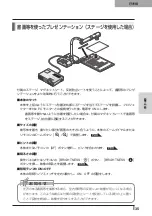
顕微鏡を使ったプレゼンテーション

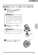
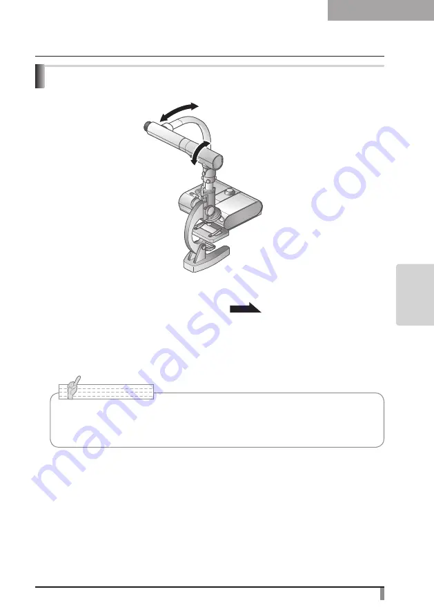
■顕微鏡のセット

顕微鏡にプレパラート等の撮影したいものを乗せて目視で顕微鏡側のピントを合わせます。

付属の顕微鏡アタッチメントを取り付けます。


P.45

■本体のセット

プロジェクターまたは PC モニターとの接続を行った後、電源を ON にします。

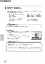
■顕微鏡モードへの変更

OSD で[顕微鏡](Microscope)→[Set]を選択します。

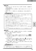
■ピントの調整

本体またはリモコンの[AF]ボタンでピントを合わせます。

■明るさの調整

顕微鏡側のミラーで明るさを調整します。

お 知 ら せ

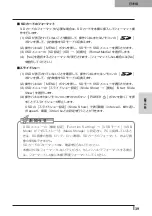
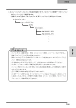
・..本体レンズが顕微鏡アタッチメントに当たらないように注意してください。
・.顕微鏡モードへ変更すると、

[映像モード]

(Image.Mode)は自動的に[カラー書類 1]

(Graphics1)が選択されます。

調整

調整

Summary of Contents for L-1EX

Page 1: ...d werden ggf rechtlich verfolgt OVERSEAS SUBSIDIARY COMPANIES U S A ELMO USA CORP Headquarters 1478 Old Country Road Plainview NY 11803 5034 U S A Tel 516 501 1400 Fax 516 501 0429 E mail elmo elmousa...

Page 2: ......

Page 3: ......

Page 4: ......

Page 5: ...AC AC...

Page 6: ...AC AC AC AC AC AC...

Page 7: ...AC AC AC AC AC...

Page 8: ...AC AC AC AC AC AC...

Page 9: ...AC AC AC100V 50Hz 60Hz 0 40 30 85 CMOS CMOS AC FD MO MD...

Page 10: ...CD DVD LED SD Ni Cd 4...

Page 11: ...1 11 11 12 12 14 15 16 17 OSD On Screen Display 19 Camera OSD 21 SD OSD 25 SD 26 2 28 28 AC 30 3 32 32 4 34 34 35 SD 36 USB SD 40 USB PC 42 43 45 47 48 5 49 49 50 50 51 51 52 53 53 53 54 55 Auto 55 On...

Page 12: ...10 Manual 55 56 56 57 58 60 61 PinP 62 63 6 64 64 7 66 66 67 67 68 68...

Page 13: ...11 P 15 P 35 P 49 P 35 AF P 50 P 35 P 16 P 12 P 45 P 35 Image Mate CD ROM P 14 1...

Page 14: ...12...

Page 15: ...13 POWER ON OFF ON OFF ON OFF SD SD SD SD LED P 54 OSD P 19 MENU OSD OSD LED P 19 CAMERA LED P 54 OSD PC RGB IN RGB IN LED P 54 OSD P 53 P 53 SD P 37 SD SD 4 4 SD 4 4 SD 4 4...

Page 16: ...14 DC IN 12V AC RGB OUT RGB PC RGB P 30 RGB IN RGB PC RGB P 30 VIDEO OUT RCA TV NTSC PAL P 31 USB 2 0 Image Mate CD ROM P 42 RESOLUTION SXGA 1280 1024 WXGA 1280 800 XGA 1024 768 RECORDER...

Page 17: ...15 SD SD RGB VIDEO RGB VIDEO RGB RGB OUT VIDEO OUT RGB OUT VIDEO OUT RGB VIDEO VIDEO RGB IN RGB OUT PC RGB OUT PC VIDEO CAMERA...

Page 18: ...16 4 2 4...

Page 19: ...17 ON OFF ON OFF SD SD 4 4 2 ZOOM P 49 OSD P 49 BRIGHT NESS P 53 P 53 SD SD PinP OSD SD SD P 54 PC RGB IN P 54 SD P 37 3 AF P 50 PinP SD 2 SD 3...

Page 20: ...18 7 30 7m 30 3 0 3 0 3 0 3 0 3 0 3 0 3 0 3 0...

Page 21: ...19 OSD On Screen Display OSD OSD OSD OSD OSD 1 MENU OSD 2 MENU...

Page 22: ...20 1 2...

Page 23: ...21 Image Setting Function Setting Back OSD MENU OSD P 54 Camera OSD...

Page 24: ...ess Auto Manual Reset Brightness AF AF Mode Push AF Zoom Sync Focus White Balance Auto One Push Manual R Gain B Gain Image Mode 1 Text1 2 Text2 3 Text3 1 Graphics1 2 Graphics2 DLP Edge Effect 1 Low Mi...

Page 25: ...23 Gamma 1 Low Middle High Image Rotation Off ON 180 On Microscope Off SET Set Color B W Color B W Posi Nega Posi Nega Back OSD...

Page 26: ...USB USB Mode Mass Storage USB SD Application USB Flickerless 60Hz 50Hz Video Format NTSC VIDEO NTSC PAL VIDEO PAL Highlight Darkness Size Mask Darkness Scroll 2 2 3 4 3 4 Preset 1 2 3 ON Power On Exit...

Page 27: ...25 Call 1 2 3 ON Power On Default Exit Guide On ON Off Language OSD English OSD Back OSD SD MENU OSD P 54 SD OSD SD SD SD SD Slide Show Back OSD OSD ON...

Page 28: ...26 Delete Current Yes No All SD Yes No Exit Lock Current All SD Exit Unlock Current All SD Exit Format Media SD Yes No SD Back OSD Yes No Yes No SD...

Page 29: ...27 Start Slide Show Interval 5sec 10sec 15sec 30sec Select All SD Locked Only SD Repeat Off 1 On Order Forward Backward Back OSD...

Page 30: ...28 1 2 90 180 2...

Page 31: ...29 3 AC DC IN 12V AC P 30 POWER 4 POWER ON POWER ON...

Page 32: ...30 AC RGB RGB OUT RGB PC RGB RGB IN RGB RGB OUT DC IN 12V VIDEO OUT TV RGB IN USB PC PC PC PC...

Page 33: ...0 USB USB RGB OUT VIDEO OUT RGB VIDEO P 15 AC OFF AC AC AC DC DC IN 12V AC RGB RGB IN 10 9 8 7 6 5 4 3 2 1 15 14 13 DSUB 15P 12 11 0 7V p p 75 TTL TTL No No No 1 6 GND 11 GND 2 7 GND 12 N C 3 8 GND 1...

Page 34: ...32 1 POWER OFF POWER 2 OFF 2 AC AC 3 90 3 OFF...

Page 35: ...33 4 180 AC OFF...

Page 36: ...34 OFF OSD Camera 1 3 TEXT1 3 1 Graphics1 DLP 2 Graphics2 PC ON P 49 AF P 50 BRIGHTNESS BRIGHTNESS P 53 ON OFF ON OFF 4...

Page 37: ...35 PC ON P 49 AF P 50 BRIGHTNESS BRIGHTNESS P 53 ON OFF ON OFF...

Page 38: ...36 SD SD SD SD SD SD 7Mbyte SD SD SD SD SD Panasonic 512MB 1GB 2GB SDHC Panasonic 4GB 1280 1024 SXGA 1280 800 WXGA 1280 960 XGA 2048 SD SD Card Reading SD SD JPEG SD ON...

Page 39: ...37 1 2 OSD 3 ZOOM IN SD OSD Guide ON SD SD SD SD SD SD SD 1 16 4 4 2 1 OSD SD SD 2 OSD 3 AF SD AF...

Page 40: ...38 1 SD OSD AF 4 4 2 3 AF 1 OSD SD SD 4 4 AF 4 4 2 4 4 3 MENU SD OSD OSD SD SD Delete Current All Yes No OSD SD SD Lock Current All OSD SD SD Unlock Current All...

Page 41: ...SD SD 2 MENU SD OSD 3 OSD SD SD Format Media 4 Yes No 1 OSD SD 2 MENU SD OSD 3 OSD Slide Show Start Slide Show 4 POWER OSD Slide Show Interval Repeat Order OSD Function Setting USB USB Mode Mass Stora...

Page 42: ...40 USB SD USB SD Microsoft OS Windows 2000 SP4 XP SP2 Vista 1 2 USB OSD Camera USB USB Mode Mass Storage SD Windows 2...

Page 43: ...41 USB USB OSD USB USB Mode USB USB2 0 USB USB USB Mode Mass Storage PC SD 3 SD JPEG DCIM 100 ELMO IMAG0001 JPG IMAG0002 JPG...

Page 44: ...42 USB PC USB USB USB2 0 USB Image Mate CD ROM CD ROM Image Mate TWAIN Image Mate TWAIN OS Image Mate CD ROM HELP OSD USB USB Mode Application...

Page 45: ...43 P 45 PC ON OSD Microscope Set AF Image Mode 1 Graphics1...

Page 46: ...44 OSD Microscope Off OSD Microscope Off Image Mode Image Mode Microscope BRIGHTNESS BRIGHTNESS...

Page 47: ...45 1 2 3...

Page 48: ...46 4 5 20mm 28mm...

Page 49: ...47 PC ON AF OSD Focus Manual P 50 BRIGHTNESS BRIGHTNESS P 53 ON OFF ON OFF 50mm...

Page 50: ...48 OSD Image Rotation On 180 110 110 50mm OFF...

Page 51: ...49 ZOOM OUT ZOOM IN 5 2 8 SD SD 5 L 1ex...

Page 52: ...50 AF 50mm SD SD...

Page 53: ...51 OSD Focus OSD AF AF Mode Zoom Sync...

Page 54: ...52 ON OFF ON OFF OFF LED LED ON OFF ON OFF...

Page 55: ...53 BRIGHTNESS BRIGHTNESS OSD Brightness OSD Brightness Auto OSD Brightness Manual Auto OSD Guide On BRIGHTNESS BRIGHTNESS OSD Reset Brightness BRIGHTNESS...

Page 56: ...54 RGB RGB IN SD RGB RGB IN RGB VIDEO VIDEO PC PC RGB OUT PC VIDEO CAMERA...

Page 57: ...55 Auto Auto One Push OSD White Balance One Push Manual OSD White Balance Manual OSD R Gain B Gain 3000K 8000K OSD Guide On...

Page 58: ...56 OSD Preset 1 3 USB OSD Preset ON Power On USB 4 1 3 ON AF E x i t O N 3 2 1 ZOOM IN...

Page 59: ...57 OSD Call 1 3 OSD Call ON Power On OSD Call Default USB E x i t O N 3 2 1...

Page 60: ...58 OSD Function Setting Highlight Darkness Size...

Page 61: ...59 SD PC OSD...

Page 62: ...60 OSD Function Setting Mask Darkness SD PC...

Page 63: ...61 OSD Function Setting Scroll 2 3 4 SD PC...

Page 64: ...62 PinP 1 4 PinP 1 4 PinP PinP SD PC PinP 1 4...

Page 65: ...63 RGB 1 OFF 2 3 ON 1 2 MENU ENTER...

Page 66: ...64 AC AC OFF ON OFF ON RGB VIDEO RGB VIDEO RGB VIDEO P 15 USB USB SD USB SD USB SD P 24 P 51 PAL PAL NTSC PAL BRIGHTNESS CMOS 6...

Page 67: ...65 SD SD SD SD SD 2 1 2 LED...

Page 68: ...66 DC12V AC AC100 240V 15W AC 350mm 370 5mm 411 5mm 195mm 254 5mm 444 5mm 2 9kg 1 RGB Dsub 15P 1 RCA 75 1 NTSC PAL RGB Dsub 15P 1 USB B SD RCA EIAJ RC 6703 7...

Page 69: ...56mm XGA 417mm 309mm 92mm 69mm 50mm 5 2 8 1 3 CMOS 1384 1076 149 1329 1049 RGB 800TV 800TV 500TV RGB RGB 0 7 V p p 75 SXGA WXGA XGA SXGA 1280 1024 60Hz 63 981kHz 60 020Hz WXGA 1280 800 60Hz 49 306kHz...

Page 70: ...lectronics Standards Association SD 550 0014 12 23 7 06 7670 0025 108 0073 12 16 4 03 3453 6471 467 8567 6 1 4 052 811 5261 540 0039 2 4 06 6942 3221 980 0023 1 18 4 022 266 3255 730 0041 5 8 2 082 24...

Page 71: ...ORING OPERATION PROCEDURE VARIOUS FUNCTIONS AND OPERATIONS TROUBLE SHOOTING SPECIFICATIONS English Document Camera INSTRUCTION MANUAL Please read this instruction manual carefully before using this pr...

Page 72: ...sement or near a swimming pool and the like Placement Do not place this product on an unstable cart stand tripod bracket or table The product may fall causing serious injury to a child or adult and se...

Page 73: ...your electrician to replace your obsolete outlet Do not defeat the safety purpose of the grounding type plug Power Cord Protection Power supply cords should be routed so that they are not likely to b...

Page 74: ...ols may result in damage and will often require extensive work by a qualified technician to restore the product to its normal operation If the product has been dropped or damaged in any way When the p...

Page 75: ...ateral triangle is intended to alert the user to the presence of uninsulated dangerous voltage within the product s enclosure that may be of sufficient magnitude to constitute a risk of electric shock...

Page 76: ...iate radio frequency energy and if not installed and used in accordance with the instructions may cause harmful interference to radio or television reception However there is no guarantee that interfe...

Page 77: ...d on the screen it is a phenomenon peculiar to the CMOS Area Image Sensors and is not a malfunction n Follow the guidelines below to prevent the unit from dropping or overturning Use the product on a...

Page 78: ...ent Insert from one side and pay particular attention to the polarity directions Be sure to use AAA batteries n If any liquid from a battery leaks onto your skin or clothes flush the area with clean w...

Page 79: ...n using printed materials etc 102 Presentation using printed materials etc Using the stage 103 Presentation using an SD card commercially available 104 Transferring images from the SD card to a USB co...

Page 80: ...ighlight operations 127 Mask Function 128 Mask settings 128 Mask operations 128 Scroll Function 129 Digital zoom settings 129 Scroll operations 129 PinP Picture in Picture Function 130 PinP operations...

Page 81: ...agnetic strip P 103 3 Zoom dial P 117 11 Stage P 103 4 AF Button P 118 12 Anti glare sheet P 103 5 Camera column 13 Remote control P 84 6 Operating panel P 80 14 Microscope attachment P 113 7 Stage po...

Page 82: ...80 PART NAMES AND FUNCTIONS English Functions 1 2 6 7 8 11 13 3 9 4 5 14 10 12 Operating Panel...

Page 83: ...image The LED is lit in CAMERA mode P 122 3 Direction To select an OSD menu item 9 PC To switch the output image to the image input to RGB IN The LED is lit in PC mode P 122 4 Enter To decide the OSD...

Page 84: ...Video Output Terminal To output images to an NTSC PAL system monitor e g TV monitor P 99 5 USB 2 0 Compliant To transfer image to a PC or control the main unit from a PC using the Image Mate software...

Page 85: ...o t e Only one image can be output at a time either RGB OUT or VIDEO OUT RGB OUT and VIDEO OUT cannot be output simultaneously When the RGB VIDEO switch is set to VIDEO the image input to RGB IN is no...

Page 86: ...ns Do not use new and old batteries or batteries of different types together Be sure to use AAA batteries Replace the batteries with new ones at least once a year Use the supplied batteries only for a...

Page 87: ...kward through the images saved in SD mode Highlight mode To move highlighted area Mask mode To move masked area Scroll mode To scroll displayed image PinP mode To move the small screen Recorder mode T...

Page 88: ...d sensor Angle Within 30 up down left and right from the infrared sensor within 7m 30 3 0 3 0 3 0 3 0 3 0 3 0 3 0 3 0 N o t e The receivable range may be reduced when the main unit is placed in direct...

Page 89: ...ress the MENU button on the front panel to display the OSD menu and then use the buttons to move the cursor to the icon you want to operate or set 2 Press the Enter button on the front panel to select...

Page 90: ...1 Use the buttons on the front panel to adjust the setting value 2 Press the Enter button again on the front panel to adjust the value as indicated on the level bar Set the level Increase the level ba...

Page 91: ...splay the menu for the adjustment of cam era image Function Setting Function Setting Menu To display the menu for the setting of functions Back To hide the OSD menu Change the image mode to CAMERA mod...

Page 92: ...et the white balance to a fixed set ting after carrying out automatic correc tion Manual To manually adjust the R Gain and B Gain R Gain Color Manual Use the level bar to adjust the R Gain for the cam...

Page 93: ...rows stronger as the number is in creased Middle High Image Rotation Off Turn ON to rotate the camera image by 180 On Microscope Off SET to enter Microscope mode Set Color B W Color To output a color...

Page 94: ...size of the Highlight display Mask Darkness To set the darkness of the masked sec tion using the level bar Scroll x2 To set the digital zoom magnification for scroll display to 2x 3x or 4x x3 x4 Pres...

Page 95: ...nese English To display the OSD menu in English Back To return to the OSD menu display top menu The symbol indicates the factory settings After using Image select to change the output image to SD Mode...

Page 96: ...d Locked images cannot be deleted Exit Exit without locking anything Unlock Current To unlock the image currently being dis played All To unlock all images stored on the SD card Exit Exit without unlo...

Page 97: ...se all images stored on the SD card for the slide show Locked Only To use only locked images from the im ages stored on the SD card for the slide show Repeat Off The slide show only shown once On The...

Page 98: ...urning it Never hold the camera head N o t e Carry the product by holding the lower part of the main unit in both hands Never hold the product by the column or the camera head Pay attention to prevent...

Page 99: ...Power Socket plug the AC adapter into the wall socket P 98 The POWER button is illuminated red 4 Press the POWER button on the operating panel or the remote control After the POWER button flashes blu...

Page 100: ...analog RGB input Connect the supplied RGB cable from the RGB OUT terminal on the rear panel of the unit to the RGB input terminal of the display device If the displayed image is off center adjustment...

Page 101: ...o protect the unit and peripheral devices unplug the power plug and the AC adapter and turn off all other devices before connecting the video cable When plugging in or unplugging the power plug the AC...

Page 102: ...pproximately two seconds or more The lamp changes from blue to red and the power switches off 2 Unplug the AC adapter from the wall socket Then disconnect the AC adapter and the video cable 3 Turn the...

Page 103: ...ning it Never hold the camera head Proper storage position for the camera head is shown in the figure above Never apply excessive force to the camera Pay attention to prevent the camera head from knoc...

Page 104: ...t Set the main unit as shown in the figure above Then connect it to a projector or a PC monitor and turn on the power for the main unit n Adjusting the size Place an object on the stage and then adjus...

Page 105: ...ge and then adjust the zoom dial on the main unit or the zoom buttons on the remote control so that the part you want to shoot fits the screen size P 117 n Adjusting the focus Press the AF button on t...

Page 106: ...cannot be displayed When displaying image data in an unsupported format or is displayed on the output screen If you try displaying image data on an SD card without inserting an SD card a black screen...

Page 107: ...layed on the screen Delete any unnecessary images or use another SD card Never remove the SD card while it is reading or writing data This may cause malfunctions to occur Do not turn off the power to...

Page 108: ...on the SD card are displayed as single images When you want to work in 4 x 4 display press the button on the operating panel or the AF button on the remote control to change to 4 x 4 display 2 Use the...

Page 109: ...rating panel or on the remote control to switch the output image to SD mode 2 Press the MENU button on the operating panel to display the SD Mode OSD menu 3 From the OSD menu select Slide Show Start S...

Page 110: ...wer supply to this product and to the PC 2 Connect this product to the PC with the supplied USB cable N o t e Set USB Mode to Mass Storage on the OSD Camera settings menu Insert the SD card with the l...

Page 111: ...on We recommend using a USB 2 0 compliant USB cable Depending on the USB environment used by the PC or peripheral equipment using the USB 2 0 compliant cable image transfer may be disrupted Operation...

Page 112: ...the USB 2 0 compliant cable image transfer may be disrupted Operation is not guaranteed for all environments Image Mate can be found on the supplied CD ROM The Image Mate and TWAIN driver Image Mate...

Page 113: ...turn on the power for the main unit n Changing to Microscope mode From the OSD select Microscope Set n Adjusting the focus The AF button on the main unit or on the remote control focuses the camera on...

Page 114: ...From the OSD select Microscope Off N o t e To return to Regular mode after using the microscope set Set Off in the OSD When setting Set Off in the OSD Image Mode returns to the Image Mode selected be...

Page 115: ...he centers of the cross and the eyepiece with the screws matching the both centers Microscope Align the center N o t e The image may appear darker when viewed through this unit than when viewed with t...

Page 116: ...main unit together 5 Slide in from the side and adjust the lens for the main unit to the top surface of the microscope attachment N o t e The microscope attachment can be used when the eyepiece is 20...

Page 117: ...on the main unit or the zoom buttons on the remote control so that the part of the object you want to shoot fits the screen size n Adjusting the focus Press the AF button on the main unit or on the re...

Page 118: ...of the main unit set Image Rotation to On in the OSD to rotate the image by 180 Camera head rotation angle Forward shooting 110 from the normal downward shooting position Backward shooting 110 from t...

Page 119: ...gital zoom range the image quality is degraded In SD mode SD images can be digitally zoomed enlarged reduced TELE WIDE VARIOUS FUNCTIONS AND OPERATIONS 5 Precautions regarding the handling of L 1ex zo...

Page 120: ...ay not be brought into focus by the auto focus In such cases use the manual focus Low contrast objects Objects with fine repeated patterns such as lateral stripes and criss cross stripes Objects glitt...

Page 121: ...Focus from the OSD menu Use this function manual focus to focus on any part of a 3 D object Zoom Sync Focus You can automatically adjust the focus by selecting AF Mode Zoom Sync from the OSD menu and...

Page 122: ...n lamp switch Make sure that the light from the illumination lamp does not shine directly into their eyes This product is equipped with a high brightness LED lamp You can safely use the lamp to light...

Page 123: ...N o t e Factory setting is set to Auto Manual adjustment fixes the brightness and does not adjust to changes in brightness of the object When the brightness becomes dark the frame rate slows and the i...

Page 124: ...sing the button on the operating panel or on the remote control By connecting PCs and other devices to the analog RGB input terminal RGB IN you can switch output images without disconnecting cables N...

Page 125: ...hite Balance One Push from the OSD menu The white balance for the color temperature is then fixed How to use Manual Setting White Balance Manual from the OSD menu fixes the white balance to allow R Ga...

Page 126: ...e balance Brightness Intensity of red color when selecting White Balance Manual Image Mode Settings Intensity of blue color when selecting White Balance Manual Edge enhancement in Graphics mode Posi N...

Page 127: ...ed number Select Call Power On from the OSD menu to call the settings for when the power is turned on Select Call Default from the OSD menu to call the factory settings Excluding USB Mode settings Pow...

Page 128: ...Mode OSD Menu select Function Setting Highlight When Darkness is selected the level bar is displayed and you can then set the darkness for the areas outside the highlighted section with the and butto...

Page 129: ...ol The highlight display is cleared when you press the button on the remote control again N o t e The Highlight function cannot be used when the output image is PC In the optical zoom range the highli...

Page 130: ...press the button on the remote control while the output image is Camera Image or SD Mode the mask display uses the darkness set previously You can move the masked area using the and buttons on the rem...

Page 131: ...image expands to the digital zoom set previously You can scroll the enlarged image by using the or buttons on the remote control Digital zoom is canceled when you press the button on the remote contr...

Page 132: ...om left of the screen By using the and buttons on the remote control you can move the still image to the bottom left top left top right and bottom right PinP display is canceled when you press the but...

Page 133: ...supply to the desktop recorder and to this product 2 Connect this product to the desktop recorder using the cable supplied with the desktop recorder 3 Turn on the power supply to the desktop recorder...

Page 134: ...B mode from Mass Storage to Application refer ring to Function Setting Menu When using SD mode change the output image to Camera image P 92 The image is out of focus The document object is too close t...

Page 135: ...is not being read correctly Use the SD card after formatting it twice as described below First format the card using a computer Second format the card us ing the main unit About the lamp LED lighting...

Page 136: ...Ext control terminal USB 2 0 compliant Type B receptacle x 1 Memory Interface SD card slot x 1 Use pin plug for RCA pin in accordance with EIAJ RC 6703 Main Camera Item Specifications Lens f 3 85mm 2...

Page 137: ...60Hz Horizontal frequency 48 363kHz Vertical frequency 60 004Hz Composite video output Compliant with NTSC PAL White balance Full auto One push Manual Video output selection switch Provided NTSC PAL...

Page 138: ...8m 1 Remote control infrared wireless type 1 AAA batteries 2 Remote control strap 1 Microscope attachment 1 Microscope attachment screw 3 The above specifications are subject to change without notice...

Page 139: ...CHE RANGEMENT PROC DURES DE FONCTIONNEMENT DESCRIPTION DES FONCTIONS D PANNAGE CARACT RISTIQUES Fran ais Cam ra de document MODE D EMPLOI Veuillez lire attentivement ce mode d emploi avant d utiliser...

Page 140: ...areil pr s de l eau comme par exemple pr s d une baignoire d un lavabo d un vier de cuisine ou de buanderie dans un sous sol humide pr s d une piscine ou autres endroits similaires Support Ne pas plac...

Page 141: ...n s ou cras s par des objets plac s sur eux ou pr s d eux Veiller particuli rement aux extr mit s du cordon et sa sortie de l appareil Foudre Pour assurer la protection de l appareil contre la foudre...

Page 142: ...nu cela indique qu il n cessite l intervention d un sp cialiste Remplacement des pi ces Veiller ce que les pi ces utilis es par le r parateur soient celles sp cifi es par le fabricant ou qu elles ont...

Page 143: ...1965 Le symbole de l clair t te defl che dans un triangle quilat ral avertit l utilisateur de la pr sencede courant lectrique non isol deforte amplitude l int rieur del appareil ce qui constitue unris...

Page 144: ...ation of this device and may cause interference levels which exceed the limits established by the FCC for this equipment It is the responsibility of the user to obtain and use a shielded equipment int...

Page 145: ...s cause de l utilisation des capteurs d image de zone CMOS compos s de nombreux pixels Bien que des points lumineux ou des points noirs puissent exister sur l cran c est un ph nom ne propre aux capteu...

Page 146: ...piles neuves et usag es ni des piles de type diff rent N essayez pas de recharger ni de court circuiter les piles Lorsque les piles usag es sont mises au rebut respectez la r glementation locale en v...

Page 147: ...entation l aide de visuels imprim s 171 Pr sentation l aide de visuels imprim s Utilisation de la platine 172 Pr sentation l aide d une carte SD disponible dans le commerce 173 Transfert d images de l...

Page 148: ...sque 199 R glages de masque 199 Utilisation de la fonction masque 199 Fonction d filement 200 R glages du zoom num rique 200 Utilisation de la fonction d filement 200 Fonction PinP incrustation d imag...

Page 149: ...magn tique P 172 3 Cadran de zoom P 187 11 Platine P 172 4 Bouton AF P 188 12 Feuille antireflets P 172 5 Colonne de cam ra 13 T l commande P 152 6 Tableau de commande P 148 14 Fixation du microscope...

Page 150: ...148 NOMENCLATURE ET FONCTIONS Fran ais Fonctions 1 2 6 7 8 11 13 3 9 4 5 14 10 12 Tableau de commande...

Page 151: ...de CA MERA P 193 3 D place ment Pour s lectionner une rubrique du menu OSD 9 PC Pour commuter l image de sortie sur l image d en tr e dans RGB IN La DEL s allume en mode PC P 193 4 Validation Pour val...

Page 152: ...nnecteur de sortie vid o composite Pour envoyer les images vers un moniteur syst me NTSC PAL par exemple un t l viseur P 167 5 USB Conforme 2 0 Pour transf rer l image ou piloter l unit principale par...

Page 153: ...peut tre produite la fois quelle que soit la s lection RGB OUT ou VIDEO OUT RGB OUT et VIDEO OUT ne peuvent pas tre utilis s simultan ment Lorsque l interrupteur RGB VIDEO est r gl sur VIDEO l image d...

Page 154: ...euves et usag es ni des piles de type diff rent Utilisez uniquement des piles AAA Remplacez les piles par des neuves au moins une fois par an Utilisez les piles fournies uniquement pour la premi re v...

Page 155: ...tr es en mode SD Mode s lection pour d placer la zone s lectionn e Mode masque pour d placer la zone masqu e Mode d filement pour faire d filer l image affich e Mode PinP pour d placer le petit cran M...

Page 156: ...gle jusqu environ 30 droite gauche haut et bas partir du capteur infrarouge jusqu 7 m 30 3 0 3 0 3 0 3 0 3 0 3 0 3 0 3 0 Remarque La zone de r ception peut tre r duite lorsque l unit principale est pl...

Page 157: ...vant pour afficher le menu OSD puis utilisez les boutons pour d placer le curseur sur l ic ne que vous souhaitez utiliser ou configurer 2 Appuyez sur le bouton Validation du tableau avant pour s lecti...

Page 158: ...du tableau avant pour r gler la valeur d option 2 Appuyez de nouveau sur le bouton Validation du tableau avant pour fixer la valeur comme indiqu sur la barre de niveau R gle le niveau Augmente le r gl...

Page 159: ...le menu pour le r glage de l image cam ra Function Setting Function Setting Menu Pour afficher le menu pour le r glage des fonc tions Back Pour cacher le menu OSD Changez le mode d image sur CAMERA l...

Page 160: ...mise au point Zoom Sync La mise au point est effectu e automa tiquement pendant le zoom Focus Utilisez la barre de niveau pour affiner la mise au point White Balance Auto Pour r gler automatiquement l...

Page 161: ...s1 Low Accentue les contours de l image pour la rendre plus nette et plus claire Middle High Gamma Image Mode Graphics1 Low Pour modifier les caract ristiques de reproduction des nuances de l image L...

Page 162: ...fichage s lection Mask Darkness Pour r gler l assombrissement de la section masqu e l aide de la barre de niveau Scroll x2 Pour r gler l agrandissement du zoom num rique pour l affichage d filement su...

Page 163: ...afficher le menu OSD en anglais Back Pour revenir au menu principal du menu OSD Le symbole indique le r glage d usine Apr s avoir utilis la s lection d image pour changer l image de sortie en mode SD...

Page 164: ...rte SD Les images verrouill es ne peuvent pas tre suppri m es Exit Pour quitter sans rien verrouiller Unlock Current Pour d verrouiller l image actuellement affich e All Pour d verrouiller toutes les...

Page 165: ...tock es sur la carte SD pour le diaporama Locked Only Pour utiliser uniquement les images ver rouill es parmi les images stock es sur la carte SD pour le diaporama Repeat Off Le diaporama s affiche un...

Page 166: ...ant sa rotation Ne tenez jamais la t te de cam ra Remarque Transportez l appareil en tenant des deux mains la partie inf rieure de l unit principale Ne tenez jamais l appareil par la colonne ou la t t...

Page 167: ...tation b r a n c h e z l a d a p t a t e u r C A sur la prise murale P 166 Le bouton POWER s allume en rouge 4 Appuyez sur le bouton POWER du tableau de commande ou de la t l commande Apr s le clignot...

Page 168: ...ique d affichage Consultez le manuel d utilisation de votre p riph rique d affichage particulier pour conna tre la proc dure exacte 2 Pour raccorder l appareil n importe quel p riph rique dot d une so...

Page 169: ...bleu 13 Signal de synchronisation horizontale 4 N C 9 N C 14 Signal de synchro nisation verticale 5 GND 10 GND 15 N C 3 Pour raccorder l appareil une borne d entr e vid o composite Branchez le c ble v...

Page 170: ...il et les p riph riques d branchez la fiche d alimentation et l adaptateur CA puis mettez tous les autres dispositifs hors tension avant de brancher le c ble vid o Lors du branchement ou du d branchem...

Page 171: ...deux secondes ou plus La lampe passe du bleu au rouge et l alimentation s teint 2 D branchez l adaptateur CA de la prise murale Puis d branchez l adaptateur CA et le c ble vid o 3 Faites pivoter la t...

Page 172: ...la t te de cam ra La position de rangement correcte de la t te de cam ra est illustr e sur la figure ci dessus N exercez jamais de force excessive sur la t te de cam ra Faites attention de ne pas cog...

Page 173: ...illustr sur la figure ci dessus Ensuite raccordez la un projecteur ou un moniteur PC puis mettez l unit principale sous tension n R glage de la taille Placez un objet sur la platine et r glez sa posi...

Page 174: ...de zoom de l unit principale ou les boutons de zoom de la t l commande afin d adapter la partie de l objet photographier la taille de l cran P 187 n Mise au point Appuyez sur le bouton AF de l unit p...

Page 175: ...173 PROC DURES DE FONCTIONNEMENT Fran ais Pr sentation l aide d une carte SD disponible dans le commerce...

Page 176: ...ieure 7 Mo ne peuvent pas tre affich es Lorsque le format des images affich es n est pas pris en charge ou s affiche sur l cran de sortie Si vous tentez d afficher les donn es d image d une carte SD s...

Page 177: ...g e contre l criture il est impossible de sauvegarder des images sur la carte SD Si la carte SD est pleine lors de la sauvegarde une marque X s affiche l cran Effacez toutes les images inutiles ou uti...

Page 178: ...stock es sur la carte SD s affichent comme images uniques Si vous souhaitez travailler en affichage 4 x 4 appuyez sur le bouton du tableau de commande ou sur le bouton AF de la t l commande pour passe...

Page 179: ...raire s lectionnez No n Diaporama 1 Assurez vous que l OSD n est pas affich puis appuyez sur le bouton du tableau de commande ou de la t l commande pour commuter l image de sortie en mode SD 2 Appuyez...

Page 180: ...appareil sous tension ainsi que le PC 2 Raccordez cet appareil au PC avec le c ble USB fourni Remarque R glez USB Mode sur Mass Storage dans le menu OSD du mode cam ra Ins rez la carte SD en orientan...

Page 181: ...ct via USB Nous recommandons d utiliser un c ble USB conforme 2 0 Selon l environnement USB du PC ou du p riph rique utilisant le c ble conforme USB 2 0 le transfert d image risque d tre perturb Le fo...

Page 182: ...le transfert d image risque d tre perturb Le fonctionnement n est pas garanti pour tous les environnements Image Mate est disponible sur le CD ROM fourni Le logiciel Image Mate et le pilote TWAIN dest...

Page 183: ...ttez la sous tension n Passage en mode microscope Dans l OSD s lectionnez Microscope Set n Mise au point Appuyez sur le bouton AF de l unit principale ou de la t l commande pour effectuer la mise au p...

Page 184: ...cope Dans l OSD s lectionnez Microscope Off Remarque Pour revenir au mode normal apr s avoir utilis le microscope r glez Set Off dans l OSD Lors du r glage de Set Off dans l OSD Image Mode revient sur...

Page 185: ...leton de vis e l aide des vis qui doivent tre align es avec les deux centres Microscope Aligner le centre Remarque L image risque d appara tre plus sombre si elle est observ e avec cet appareil plut t...

Page 186: ...5 Faites glisser lat ralement l objectif de l unit principale et positionnez le sur la surface sup rieure de la fixation du microscope Remarque La fixation du microscope peut tre utilis e lorsque l il...

Page 187: ...e zoom de la t l commande de fa on adapter la partie de l objet photographier la taille de l cran n Mise au point Appuyez sur le bouton AF de l unit principale ou de la t l commande pour effectuer la...

Page 188: ...e Rotation sur On dans l OSD de mani re pivoter l image de 180 Angle de rotation de la t te de cam ra Prise de vue vers l avant 110 par rapport la position normale de prise de vue vers le bas prise de...

Page 189: ...que En mode SD il est possible d utiliser le zoom num rique sur les images SD agrandissement et r duction DESCRIPTION DES FONCTIONS 5 TELE WIDE Pr cautions concernant la manipulation du cadran de zoom...

Page 190: ...ci dessous ne peuvent pas toujours b n ficier de la mise au point automatique Dans un tel cas utilisez la mise au point manuelle Objets faible contraste Objets compos s de motifs fins r p t s comme d...

Page 191: ...au point manuelle pour effectuer la mise au point sur n importe quelle partie d un objet en 3D Mise au point de zoom avec synchronisation Vous pouvez effectuer automatiquement la mise au point en s le...

Page 192: ...ssurez vous que la lumi re provenant de la lampe d clairage ne soit pas directement envoy e dans leurs yeux Ce produit est quip d une lampe DEL forte intensit lumineuse Vous pouvez utiliser cette lamp...

Page 193: ...l image Les deux modes de r glage suivants peuvent tre d finis en s lectionnant Brightness dans le menu OSD R glage automatique de la luminosit Brightness Auto dans l OSD La luminosit de l image chang...

Page 194: ...de r glage s affichent l cran Pour revenir aux r glages d usine appuyez simultan ment sur les boutons BRIGHTNESS et BRI GHTNESS du tableau de commande ou r initialisez Reset Brightness dans le menu O...

Page 195: ...l commande En raccordant des PC et d autres dispositifs au connecteur d entr e RGB analogique RGB IN vous pouvez commuter des images de sortie sans d brancher les c bles Remarque Les boutons du table...

Page 196: ...glez White Balance One Push dans le menu OSD L quilibre des blancs pour cette temp rature de couleur est alors d fini Utilisation de Manual Le r glage White Balance Manual dans le menu OSD d finit l q...

Page 197: ...s Luminosit Intensit de la couleur rouge si White Balance Manual est s lectionn R glages Image Mode Intensit de la couleur bleue si White Balance Manual est s lectionn Renforcement des contours en mod...

Page 198: ...Power On dans le menu OSD pour rappeler les r glages de la mise sous tension S lectionnez Call Default dans le menu OSD pour rappeler les r glages d usine par d faut l exception des r glages du mode...

Page 199: ...m ra s lectionnez Function Setting Highlight Lorsque Darkness est s lectionn la barre de niveau s affiche et vous pouvez alors d finir l assombrissement pour les parties en dehors de la zone en surbri...

Page 200: ...n surbrillance est effac lorsque vous appuyez de nouveau sur le bouton de la t l commande Remarque La fonction surbrillance ne peut pas tre utilis e lorsque l image de sortie est r gl e sur PC Dans la...

Page 201: ...mmande lorsque l image de sortie est r gl e sur image cam ra ou mode SD l affichage du masque utilise l assombrissement d fini pr c demment Vous pouvez d placer la zone masqu e en utilisant les bouton...

Page 202: ...en fonction du zoom num rique d fini pr c demment Vous pouvez faire d filer l image agrandie en utilisant les boutons ou de la t l commande Le zoom num rique est annul si vous appuyez sur le bouton de...

Page 203: ...et de la t l commande vous pouvez d placer l image incrust e de l angle inf rieur gauche vers l angle sup rieur gauche l angle sup rieur droit et l angle inf rieur droit L affichage PinP est effac lor...

Page 204: ...s tension ainsi que l enregistreur de bureau 2 Raccordez cet appareil l enregistreur de bureau via le c ble fourni avec l enregistreur de bureau 3 Mettez cet appareil sous tension ainsi que l enregist...

Page 205: ...Storage Application comme indiqu dans la section Menu Function Setting Si vous utilisez le mode SD changez l image de sortie pour image cam ra P 160 L image est floue Le document objet est trop proche...

Page 206: ...la carte SD apr s l avoir format e deux fois comme d crit ci dessous Tout d abord formatez la carte avec un ordinateur Ensuite forma tez la carte avec l unit principale propos de la lampe clairage DEL...

Page 207: ...moire Fente de lecture de carte SD x 1 Utilisez une fiche broches RCA conforme la norme EIAJ RC 6703 Cam ra principale l ment Caract ristiques Objectif f 3 85 mm 20 02 mm zoom 5 2 fois F 2 8 3 2 Caden...

Page 208: ...s White Balance Enti rement automatique Auto Une pression One Push Manuel Manual Interrupteur de s lec tion de sortie vid o Disponible NTSC PAL Contr le de la lumino sit Brightness Automatique Auto av...

Page 209: ...mande de type infrarouge 1 Piles AAA 2 Sangle de la t l commande 1 Fixation du microscope 1 Vis de fixation du microscope 3 Les caract ristiques ci dessus sont sujettes modification sans pr avis Marqu...

Page 210: ......

Page 211: ...INBETRIEBNAHME VERSCHIEDENE FUNKTIONEN FEHLER BEHEBUNG TECHNISCHE DATEN Deutsch Dokumentenkamera BEDIENUNGSANLEITUNG Lesen Sie bitte diese Bedienungsanleitung sorgf ltig durch bevor Sie dieses Produkt...

Page 212: ...feuchten Keller oder in der N he eines Schwimmbeckens usw Platzierung Platzieren Sie dieses Produkt nicht auf einem instabilen Wagen St nder Stativ Halter oder Tisch Das Produkt k nnte herunterfallen...

Page 213: ...drige geerdete Netzstecker passt in eine geerdete Steckdose Dies ist ein Sicherheitsmerkmal Wenn Sie den Netzstecker nicht in die Steckdose hineinstecken k nnen wenden Sie sich an Ihren Elektriker um...

Page 214: ...gsanweisungen nicht ordnungsgem funktioniert Stellen Sie nur die Regler ein die in der Bedienungsanleitung behandelt werden Eine unsachgem e Einstellung von anderen Reglern kann zu Sch den f hren und...

Page 215: ...mit einem Pfeil in einem gleichseitigen Dreieck soll den Benutzer auf das Vorhandensein einer nicht isolierten gef hrlichen Spannung im Geh use des Ger tes hinweisen die stark genug sein kann um die...

Page 216: ...s berschreiten der St rgr enpegel verursachen die f r diese Ger te durch die FCC festgelegt sind Es liegt in der Verantwortung des Benutzers ein abgeschirmtes Schnittstellenger tekabel zu besorgen und...

Page 217: ...icht ordnungsgem funktionieren Daher ist das Erscheinen leuchtender oder schwarzer Punkte auf dem Bildschirm ein f r CMOS Bildsensorfl chen typisches Ph nomen und keine Fehlfunktion n Folgen Sie unten...

Page 218: ...ie sie von der Seite aus ein und achten Sie auf die korrekte Lage der Pole Richtung Verwenden Sie ausschlie lich AAA Batterien n Sollte Batteriefl ssigkeit an Ihrer Haut oder Kleidung haften bleiben r...

Page 219: ...Pr sentation mit Druckmaterial usw mit Objekthalter 244 Pr sentation mit einer SD Karte im Handel erh ltlich 245 bertragen von Bildern von der SD Karte auf einen ber USB angeschlossenen PC 250 Pr sent...

Page 220: ...Highlight Funktionen 270 Masken Funktion 271 Masken Einstellungen 271 Masken Funktionen 271 Scroll Funktion 272 Digitalzoom Einstellungen 272 Scroll Funktionen 272 PinP Bild in Bild Funktion 273 PinP...

Page 221: ...reifen S 244 3 Zoom Drehknopf S 259 11 Objekthalter S 244 4 AF Taste S 260 12 Blendschutzfolie S 244 5 Kameras ule 13 Fernbedienung S 224 6 Bedienfeld S 220 14 Mikroskop Adapter S 255 7 Einschub Objek...

Page 222: ...220 NAMEN DER TEILE UND FUNKTIONEN Deutsch Funktionen 1 2 6 7 8 11 13 3 9 4 5 14 10 12 Bedienfeld...

Page 223: ...altet S 265 3 Richtung Zur Wahl eines OSD Men punkts 9 PC Zum Umschalten des Ausgabebilds auf das an RGB IN eingespei ste Bild Die LED ist im PC Modus eingeschaltet S 265 4 Eingeben Zur Festlegung des...

Page 224: ...Videoausgang Zur Ausgabe von Bildern an einen NTSC PAL System monitor z B Fernsehmonitor S 239 5 USB 2 0 kompatibel Zur bertragung des Bildes auf einen PC oder der Steuerung des Hauptger ts von einem...

Page 225: ...is Es kann nur ein Bild gleichzeitig ausgegeben werden entweder RGB OUT oder VIDEO OUT RGB OUT und VIDEO OUT k nnen nicht gleichzeitig ausgegeben werden Wenn der Schalter RGB VIDEO auf VIDEO steht wir...

Page 226: ...en und gebrauchten Batterien oder verschiedenen Batteriearten gleichzeitig Verwenden Sie ausschlie lich AAA Batterien Wechseln Sie die Batterien mindestens einmal im Jahr gegen Neue aus Legen Sie die...

Page 227: ...r Hervorhebemodus Zum Verschieben des hervorgeho benen Teils Maskenmodus Zum Ver schieben des abgedeckten Teils Scroll Modus Zum durchbl t tern des angezeigten Bilds PinP Modus Zum Verschie ben der kl...

Page 228: ...links und rechts vom Infrarotsensor innerhalb 7m 30 3 0 3 0 3 0 3 0 3 0 3 0 3 0 3 0 Hinweis Der Empfangsbereich k nnte verringert werden wenn das Hauptger t bei direkter Sonneneinstrahlung in der N h...

Page 229: ...Bildschirmanzeige aufzurufen und bewegen Sie dann den Cursor mit den Tasten zu dem Symbol das Sie aktivieren oder einstellen m chten 2 Dr cken Sie die Taste Enter auf dem vorderen Bedienfeld um die Fu...

Page 230: ...asten auf dem vorderen Bedienfeld ein 2 Dr cken Sie die Taste Enter auf dem vorderen Bedienfeld erneut um den Wert wie auf der Pegelanzeige angegeben einzustellen Setzen Sie die Einstellung der Pegela...

Page 231: ...Men s f r die Einstellung des Kamerabildes Function Setting Function Setting Menu Zur Anzeige des Men s f r das Einstellen von Funktionen Back Ausblenden des OSD Men s Schalten Sie den Bildmodus mit d...

Page 232: ...ma tisch scharfzustellen Zoom Sync Beim Zoomen wird automatisch scharf gestellt Focus Stellen Sie mit der Pegelanzeige voll st ndig scharf White Balance Auto Zum automatischen Abgleichen des Wei werts...

Page 233: ...Konturen der Bilder indem sie sch rfer und klarer dargestellt wer den Middle High Gamma Image Mode Graphics1 Low Zur nderung der Tonwiedergabemerk male des Bildes Mit Erh hung des Werts wird der Effe...

Page 234: ...ung der Gr e der Hervorhebeanzeige Mask Darkness Zur Einstellung der Schw rze des abge deckten Teils mit der Pegelanzeige Scroll x2 Zur Einstellung der Digialzoom Vergr erung der Scroll Anzeige auf 2x...

Page 235: ...SD Men s auf Japanisch English Zur Anzeige des OSD Men s auf Englisch Back Zur R ckkehr zur OSD Hauptmen an zeige Das Symbol zeigt die Einstellung ab Werk an Schalten Sie zun chst mit Bild w hlen das...

Page 236: ...Bilder Gesperrte Bilder k nnen nicht gel scht werden Exit Verlassen ohne etwas zu sperren Unlock Current Zum Entsperren des aktuell angezeigten Bildes All Zum Entsperren aller auf der SD Karte gespeic...

Page 237: ...D Karte gespeicherten Bil der werden f r die Diashow verwendet Locked Only Nur die gesperrten Bilder der auf der SD Karte gespeicherten Bilder werden f r die Diashow verwendet Repeat Off Die Diashow w...

Page 238: ...Sie das Produkt keinesfalls am Kamerakopf fest Hinweis Halten Sie das Produkt beim Transport mit beiden H nden am unteren Teil des Hauptger ts fest Halten Sie das Produkt keinesfalls an der S ule ode...

Page 239: ...se und stecken Sie dann das Netzteil in die Steckdose S 238 Die Taste POWER leuchtet rot 4 Dr cken Sie die Taste POWER auf dem Bedienfeld oder der Fernbedienung Die Taste POWER blinkt zun chst blau un...

Page 240: ...Anzeigeger ts manuell einstellt Einzelheiten zur ordnungsgem en Durchf hrung entnehmen Sie bitte dem Benutzerhandbuch Ihres Anzeigeger tes 2 Zum Anschlie en der Einheit an Ger te mit analogem RGB Aus...

Page 241: ...2 0 kompatiblen USB Kabel angeschlossenen PC oder Peripherieger t verwendet wird kann die Bild bertragung Aussetzer aufweisen Der Betrieb wird nicht f r alle Umgebungen gew hrleistet n Spezifikationen...

Page 242: ...Peripherieger te den Netzstecker und das Netzteil heraus und schalten Sie alle anderen Ger te aus bevor Sie das Videokabel anschlie en Halten Sie beim Ein oder Ausstecken des Netzsteckers Netzteils o...

Page 243: ...l nger gedr ckt Die Leuchte wechselt von blau zu rot und der Strom wird ausgeschaltet 2 Ziehen Sie das Netzteil aus der Steckdose Ziehen Sie dann das Netzteil und das Videokabel aus dem Ger t 3 Drehe...

Page 244: ...alten Sie das Produkt keinesfalls am Kamerakopf fest Auf der oberen Abbildung wird die korrekte Lagerposition des Kamerakopfs dargestellt ben Sie keinesfalls Gewalt auf die Kamera aus Achten Sie darau...

Page 245: ...Hauptger t wie auf der unteren Abbildung dargestellt auf Schlie en Sie es dann an einen Projektor oder PC Monitor an und schalten Sie es ein n Einstellung der Gr e Legen Sie etwas auf den Objekthalte...

Page 246: ...n den Zoom Drehknopf am Hauptger t oder die Zoomtasten auf der Fernbedienung so ein dass der Teil den Sie aufnehmen m chten die Anzeige ausf llt S 259 n Einstellung des Fokus Dr cken Sie die Taste AF...

Page 247: ...245 INBETRIEBNAHME Deutsch Pr sentation mit einer SD Karte im Handel erh ltlich...

Page 248: ...werden die 7 MB gro oder gr er sind Bei Anzeige von Bilddaten in einem nicht unterst tzten Format erscheint auf der Ausgabeanzeige oder Wenn Sie versuchen Bilddaten einer SD Karte anzuzeigen ohne dass...

Page 249: ...ichert werden Wenn die SD Karte w hrend der Aufnahme voll wird wird das Zeichen X angezeigt L schen Sie alle unn tigen Bilder oder verwenden Sie eine andere SD Karte Ziehen Sie die SD Karte keinesfall...

Page 250: ...auf der SD Karte gespeicherten Bilder werden als Einzelbilder angezeigt Wenn Sie mit der Anzeige 4 x 4 arbeiten m chten dr cken Sie die Taste auf dem Bedienfeld oder die Taste AF auf der Fernbedienun...

Page 251: ...us aufzurufen 3 W hlen Sie im OSD Men Slide Show Start Slide Show 4 Wird irgendeine Taste au er der Taste POWER auf dem Bedienfeld oder der Fernbedienung gedr ckt wird die Diashow gestoppt Sie k nnen...

Page 252: ...nd den Strom des PCs ein 2 Schlie en Sie dieses Produkt mit dem mitgelieferten USB Kabel an den PC an Hinweis Stellen Sie USB Mode im OSD Kameraeinstellmen auf Mass Storage Stecken Sie die SD Karte mi...

Page 253: ...en ist Wir empfehlen die Verwendung eines USB 2 0 kompatiblen USB Kabels Abh ngig von der USB Umgebung die von dem mit dem USB 2 0 kompatiblen USB Kabel angeschlossenen PC oder Peripherieger t verwend...

Page 254: ...eripherieger t verwendet wird kann die Bild bertragung Aussetzer aufweisen Der Betrieb wird nicht f r alle Umgebungen gew hrleistet Image Mate befindet sich auf der mitgelieferten CD ROM Die Image Mat...

Page 255: ...es ein n Wechsel zum Mikroskop Modus W hlen Sie auf der Bildschirmanzeige Microscope Set n Einstellung des Fokus Die Taste AF am Hauptger t oder auf der Fernbedienung stellt die Kamera auf das Motiv s...

Page 256: ...croscope Off Hinweis Zur R ckkehr zum Normalen Modus nach Verwendung des Mikroskops stellen Sie auf der Bildschirmanzeige Set Off ein Wenn Sie Set Off auf der Bildschirmanzeige einstellen wird Image M...

Page 257: ...es Kreuzes und des Okulars mit den Schrauben aufeinander aus Mikroskop Richten Sie die Mitte aus Hinweis Das Bild kann beim Anschauen durch das Ger t dunkler erscheinen als wenn es mit blo em Auge bet...

Page 258: ...uf einer H he sind 5 Schieben Sie es von der Seite herein und stellen Sie das Objektiv des Hauptger ts ber den Mikroskop Adapter Hinweis Der Mikroskop Adapter kann verwendet werden wenn das Okular 20...

Page 259: ...der die Zoomtasten auf der Fernbedienung so ein dass der Teil des Motivs den Sie aufnehmen m chten die Anzeige ausf llt n Einstellung des Fokus Dr cken Sie die Taste AF am Hauptger t oder auf der Fern...

Page 260: ...or dem Hauptger t auf der Bildschirmanzeige Image Rotation auf On um das Bild um 180 zu drehen Drehwinkel des Kamerakopfs Aufnahme nach vorn 110 von der normalen Aufnahmeposition nach unten Aufnahme n...

Page 261: ...SD Bilder digital gezoomt vergr ert verkleinert werden VERSCHIEDENE FUNKTIONEN 5 TELE WIDE Sicherheitshinweise zum Umgang mit dem Zoom Drehknopf L 1ex Um das Aus ben von berm iger Gewalt auf den Zoom...

Page 262: ...tofokus scharfgestellt Verwenden Sie in solchen F llen die manuelle Scharfstellung Motive mit niedrigem Kontrast Motive mit schmalen sich wiederholenden Mustern z B L ngsstreifen und Querstreifen Gl n...

Page 263: ...Funktion manuelle Scharfstellung zum Scharfstellen eines beliebigen Teils des 3 D Motivs Zoom Sync Scharfstellung Sie k nnen die automatische Scharfstellung einsetzen indem Sie AF Mode Zoom Sync im OS...

Page 264: ...hten Sie darauf dass das Licht der Leuchte nicht direkt in ihre Augen f llt Dieses Produkt ist mit einer lichtstarken LED Leuchte ausger stet Diese Leuchte kann bedenkenlos zum Ausleuchten von Motiven...

Page 265: ...ahl von Brightness im OSD Men k nnen die folgenden beiden Einstellmodi gew hlt werden Automatische Helligkeitseinstellung Brightness Auto in der Bildschirmanzeige Die Helligkeit des Bildes wird automa...

Page 266: ...en erscheinen die Einstelldaten auf der Anzeige Dr cken Sie zum R cksetzen auf die Einstellungen ab Werk gleichzeitig die Tasten BRIGHTNESS und BRIGHTNESS auf dem Bedienfeld oder stellen Sie Reset Bri...

Page 267: ...nbedienung umgeschaltet werden Per Anschluss von PCs und anderer Ger te am analogen RGB Eingang RGB IN k nnen die Ausgabebilder umgeschaltet werden ohne dass daf r Kabel herausgezogen werden m ssen Hi...

Page 268: ...dann im OSD Men White Balance One Push ein Der Wei abgleich der Farbtemperatur wird dann festgesetzt Verwendung von Manual Durch die Einstellung White Balance Manual im OSD Men wird der Wei abgleich...

Page 269: ...gkeit Intensit t des Rot Tons bei Wahl von White Balance Manual Image Mode Einstellungen Intensit t des Blau Tons bei Wahl von White Balance Manual R nderverst rkung im Graphics Modus Posi Nega Einste...

Page 270: ...wer On im OSD Men um die Ein stellungen beim Einschalten des Stroms abzurufen W hlen Sie Call Default im OSD Men um die Einstel lungen ab Werk abzurufen Ausgenommen der USB Modus Einstellungen Power O...

Page 271: ...W hlen Sie im Kameramodus OSD Men Function Setting Highlight Bei Wahl von Darkness erscheint die Pegelanzeige und Sie k nnen mit den Tasten und die Schw rze der Bereiche au erhalb des hervorgehobenen...

Page 272: ...rvorhebeanzeige wird ausgeblendet wenn Sie die Taste auf der Fernbedienung erneut dr cken Hinweis Die Hervorhebe Funktion kann nicht verwendet werden wenn der PC als Ausgabebild eingestellt ist Im opt...

Page 273: ...n w hrend als Ausgabebild das Kamerabild oder SD Modus eingestellt ist verwendet die Maskenanzeige die zuvor eingestellte Schw rze Sie k nnen den abgedeckten Teil mit den Tasten und auf der Fernbedien...

Page 274: ...ingestellten digitalen Zoom vergr ert Sie k nnen das vergr erte Bild mit den Tasten oder auf der Fernbedienung durchbl ttern Der digitale Zoom wird abgebrochen wenn Sie die Taste auf der Fernbedienung...

Page 275: ...nd auf der Fernbedienung k nnen Sie das Bild nach links unten links oben rechts oben und rechts unten verschieben Die PinP Anzeige wird abgebrochen wenn Sie die Taste auf der Fernbedienung dr cken Hin...

Page 276: ...odukts aus 2 Schlie en Sie dieses Produkt mit dem zum Desktop Recorder mitgelieferten Kabel an den Desktop Recorder an 3 Schalten Sie den Strom des Desktop Recorders und dieses Produkts ein Hinweis Ei...

Page 277: ...cation wie im Funktionseinstellmen dargestellt Schalten Sie das Ausgabebild auf das Kamerabild um wenn SD Modus eingestellt ist S 232 Das Bild ist nicht scharf Das Dokument Motiv befindet sich zu nah...

Page 278: ...orrekt gelesen werden Benutzen Sie die SD Karte nachdem Sie sie zweimal formatiert ha ben wie unten beschrieben Zuerst formatieren Sie die Karte auf einem Computer Danach for matieren Sie sie mit dem...

Page 279: ...SD Kartenfach x 1 Verwenden Sie einen Steckverbinder f r RCA gem EIAJ RC 6703 Hauptkamera Punkt Technische Daten Objektiv f 3 85 mm 20 02 mm 5 2 facher Zoom F2 8 3 2 Bildwechselfrequenz Max 30 Bilder...

Page 280: ...ale Frequenz 60 004 Hz FBAS Videoausgang Kompatibel mit NTSC PAL Wei abgleich White balance Vollautomatisch Auto Einmal Dr cken One Push Manuell Manual Videoausgangs wahlschalter Vorhanden NTSC PAL He...

Page 281: ...8 m 1 Fernbedienung Infrarot kabellos 1 AAA Batterien 2 Trageriemen der Fernbedienung 1 Mikroskop Adapter 1 Mikroskop Adapterschraube 3 nderungen an den obigen technischen Daten vorbehalten Markenzeic...

Page 282: ......

Page 283: ......

Page 284: ...rletzen und werden ggf rechtlich verfolgt OVERSEAS SUBSIDIARY COMPANIES U S A ELMO USA CORP Headquarters 1478 Old Country Road Plainview NY 11803 5034 U S A Tel 516 501 1400 Fax 516 501 0429 E mail el...

Reviews: