- 30 -
●
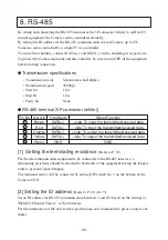
Transmission specifications
• Transmission mode
: Synchronous half duplex
• Transmission speed
: 9600bps
• Start bit
: 1 bit
• Stop bit
: 1 bit
• Parity bit
: None
By wiring and connecting the RS-485 terminal of the 5P connector (white) to an RS-485
control equipment, the Camera can be controlled externally.
By setting the ID address for the RS-485 communication in each Camera, up to 223
Cameras can be controlled by a single PC or a controller.
To assure the reliability, connect DATA(+) and DATA(-) with a shielding twist pair wire.
To protect the Camera main unit and the controller, be sure to turn OFF all the equipment
before starting connection.
●
RS-485 terminal (5P connector (white))
Code Color
Brown
Red
Orange
Yellow
Green
1
2
3
4
5
Signal Name
DATA(+)
DATA(-)
DATA(+)
DATA(-)
GND
Signal Function
+ side: To input the transmitted/received data
- side: To input the transmitted/received data
+ side: To output the transmitted/received data
- side: To output the transmitted/received data
GND
Pin No.
[1] Setting the terminating resistance
(Refer to P. 32)
For the telecommunication equipment to be connected to the RS-485 interface, a
terminating resistance should be attached to both ends of the equipment having the longest
route to prevent signal damping.
The terminal resistor will be connected by setting DIP switch No. 3 on the bottom of the
Camera to ON.
[2] Setting the ID address
(Refer to P. 20, 48, 73)
Set an ID address for RS-485 communication between 1 and 223 based on the settings of
“ELMO 1Channel Viewer” or Web browser.
For the information of the data format specifications and command list, please contact our
dealer.
8. RS-485


